


5.2 Logical Interface
C141-E224
5-23
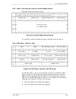
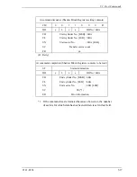
5.2.3.9 Set Device Bits – Device to Host
Error
R Status Hi R Status Lo R
I R
Reserved (0)
FIS Type (A1h)
0
SActive 31:0
1
Figure 5.11 Set Device Bits FIS
The Set Device Bits -
Device to Host FIS is used by the device to load Shadow
Command Block bits for which the device has exclusive write
access. These bits are the eight bits of the Error register and six of
the eight bits of the Status register. This FIS does not alter bit 7,
BSY, or bit 3, DRQ, of the Shadow Status register.
FIS Type -
Set to a value of A1h. Defines the rest of the FIS fields. Defines the
length of the FIS as two Dwords.
I -
Interrupt Bit. This bit signals the host adapter to enter an interrupt
pending state if both the BSY bit and the DRQ bit in the shadow
Status register are zero when the frame is received.
Error -
Contains the new value of the Error register of the Shadow
Register Block.
Status-Hi -
Contains the new value of bits 6, 5, and 4 of the Status register of
the Shadow Register Block.
Status-Lo -
Contains the new value of bits 2,1, and 0 of the Status register of
the Shadow Register Block.
SActive -
The SActive field of the Set Device Bits FIS communicates
successful completion notification for each of up to 32 queued
commands. The field is bit-significant and the device sets bit
positions to one for each command tag it is indicating successful
completion notification for. The device may set more than one bit
to one if it is explicitly aggregating successful status returns. The
device shall only indicate completion notification for a command if
it has completed successfully.
Summary of Contents for MHV2040BH
Page 1: ...C141 E224 02EN MHV2120BH MHV2100BH MHV2080BH MHV2060BH MHV2040BH DISK DRIVES PRODUCT MANUAL ...
Page 4: ...This page is intentionally left blank ...
Page 8: ...This page is intentionally left blank ...
Page 10: ...This page is intentionally left blank ...
Page 12: ...This page is intentionally left blank ...
Page 42: ...This page is intentionally left blank ...
Page 54: ...This page is intentionally left blank ...
Page 74: ...This page is intentionally left blank ...
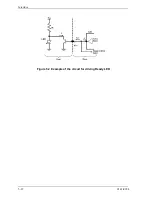
Page 86: ...Interface 5 12 C141 E224 Figure 5 2 Example of the circuit for driving Ready LED ...
Page 236: ...This page is intentionally left blank ...
Page 258: ...This page is intentionally left blank ...
Page 262: ...This page is intentionally left blank ...
Page 264: ...This page is intentionally left blank ...
Page 272: ...This page is intentionally left blank ...
Page 274: ......
Page 275: ......
Page 276: ......