


Contents
C141-C012
xiii
Illustrations
Figures
Figure 1.1 SAS drive connection patterns............................................................. 1-2
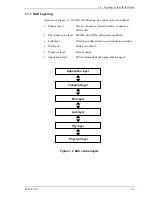
Figure 1.2 SAS control layers ............................................................................... 1-3
Figure 1.3 Physical links and phys ........................................................................ 1-4
Figure 1.4 Ports (narrow ports and wide ports)..................................................... 1-5
Figure 1.5 SAS devices ......................................................................................... 1-6
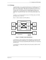
Figure 1.6 Example of potential pathways............................................................ 1-7
Figure 1.7 Reset-related terminology.................................................................. 1-12
Figure 1.8 OOB signal transmission ................................................................... 1-14
Figure 1.9 OOB signal detection ......................................................................... 1-16
Figure 1.10 SAS to SAS OOB sequence............................................................. 1-17
Figure 1.11 SAS speed negotiation window ....................................................... 1-19
Figure 1.12 SAS speed negotiation sequence (Example 1)................................. 1-21
Figure 1.13 SAS speed negotiation sequence (Example 2)................................. 1-21
Figure 1.14 Phy reset sequence (Example) ......................................................... 1-22
Figure 1.15 Connection request timeout example............................................... 1-49
Figure 1.16 Closing a connection example ......................................................... 1-50
Figure 1.17 Interlocked frames ........................................................................... 1-55
Figure 1.18 Non-interlocked frames with the same tag ...................................... 1-56
Figure 1.19 Non-interlocked frames with different tags ..................................... 1-56
Figure 1.20 Closing an SSP connection example................................................ 1-57
Figure 1.21 Example of XFER_RDY frames...................................................... 1-68
Figure 1.22 Example of TASK frame ................................................................. 1-76
Figure 1.23 Example of write command ............................................................. 1-77
Figure 1.24 Example of read command .............................................................. 1-77
Figure 1.25 Example of bidirectional command ................................................. 1-78
Figure 1.26 Example of the processing sequence for an exceptional event........ 1-80
Figure 2.1 Data space configuration.................................................................... 2-22
Figure 3.1 Data buffer configuration (in the case of 8 cache segments)............... 3-2
Figure 4.1 MODE SELECT parameter structure ................................................ 4-21
Figure 4.2 Correction of the defect descriptor .................................................. 4-167
Figure 5.1 Analysis of the termination status...................................................... 5-14
Summary of Contents for MAX3036RC SERIES
Page 4: ...This page is intentionally left blank ...
Page 128: ...This page is intentionally left blank ...
Page 136: ...This page is intentionally left blank ...
Page 338: ...This page is intentionally left blank ...
Page 368: ...This page is intentionally left blank ...
Page 378: ...This page is intentionally left blank ...
Page 380: ...This page is intentionally left blank ...
Page 394: ...This page is intentionally left blank ...
Page 396: ...This page is intentionally left blank ...
Page 398: ......
Page 399: ......
Page 400: ......