


2.1 Command Format
C141-C012
2-3
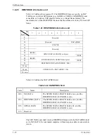
Table 2.3 12-Byte CDB basic format
Bit
Byte
7 6 5 4 3 2 1 0
0 Operation
Code
1
Reserved
0 0 0 0 0
2
Logical Block Address (MSB)
3
Logical Block Address
4
Logical Block Address
5
Logical Block Address (LSB)
6
Transfer Data Length (MSB)
7
Transfer Data Length (LSB)
8
Transfer Data Length (MSB)
9
Transfer Data Length (LSB)
10 0 0 0 0 0 0 0 0
11 Control
Byte
The meanings of each of the fields in the CDB are explained below. Depending
on the type of command, the basic format of the CDB and the definition and
meaning of a field may differ. Details are described in the specifications for
individual commands in Chapter 4.
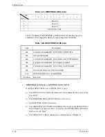
(1) Operation code
Table 2.4 Operation code
Bit
7
6 5 4 3 2 1 0
Group Code
Command Code
The top byte of all CDBs shows the format and type of command that is being
executed.
a. Group
code
The group code decides the number of bytes in the CDB and its format. The
IDD uses the commands of the groups shown below.
Group 0 (“000”): 6-byte CDB (Shown in Figure 2.1)
Group 1 (“001”): 10-byte CDB (Shown in Figure 2.2)
Group 2 (“010”): 10-byte CDB (Shown in Figure 2.2)
Summary of Contents for MAX3036RC SERIES
Page 4: ...This page is intentionally left blank ...
Page 128: ...This page is intentionally left blank ...
Page 136: ...This page is intentionally left blank ...
Page 338: ...This page is intentionally left blank ...
Page 368: ...This page is intentionally left blank ...
Page 378: ...This page is intentionally left blank ...
Page 380: ...This page is intentionally left blank ...
Page 394: ...This page is intentionally left blank ...
Page 396: ...This page is intentionally left blank ...
Page 398: ......
Page 399: ......
Page 400: ......