Treatment Process Overview
Fuji Clean’s “contact filtration” treatment is a simple, well engineered process that consists of a controlled, circuitous
flow train through anaerobic and aerobic chambers and in direct contact with assorted proprietary fixed film medias
on which biological digestion of organic matter occurs. Media is also designed and positioned to provide mechanical
filtration of process wastewater.
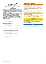
The system includes two air lift pumps (see diagram below). The Recirculating Airlift Pump returns process water and
sludge from the aerobic zone to the sedimentation chamber, recirculating 2-4 times inflow per day for CE models and
4-6 times inflow for CEN (enhanced denitrification) models. The Effluent Airlift Pump is designed to help equalize flow
and discharge treated effluent.
5
Outlet
Air
Sludge Transfer
(Recirculating air lift pumpback)
Chamber 3B
. Disinfection Chamber
(final zone before discharge – option for chlorination tablet disinfection)
Chamber 1.
Sedimentation Chamber
(separates solids and greases)
Chamber 3.
Aerobic Contact
Filtration Chamber
(both board and cylindrical hollow
mesh media) oxygen rich zone for
aerobic microbe digestion activity,
solids filtration and nitrification of
ammoniac nitrogens to nitrates
Powered by the FujiMAC “Rll” Series
Blowers
State-of-the-art linear
diaphragm air blowers manufactured
by Fuji Clean Co sized to provide
about 2.8 cubic feet per minute to
most Commercial systems.
Chamber 2.
Anaerobic Filtration Chamber
(spherical-skeleton filter media)
organic matter decomposition by
micro-organisms, suspended
solids are captured and nitrates
are denitrified
Chamber 3A
. Clarification Chamber
(settling zone)
Two Air Lift Pumps.
One Recirculating Air
Lift pump sending process water and solids
back to Chamber 1, and one Effluent Air Lift
Pump for measured discharge of treated
effluent. (See airlift pump info below).
Airlift Pumps.
This generic illustration
shows the mechanics of the “airlift
pumps” used in this system, which are
simple pipe conduits through which
pressurized air (from blower) is
introduced at the bottom and by fluid
pressure, water is carried up the pipe
by ascending bubbles.
Flow Equalization
When water level
exceeds LWL, treated
water is discharged
through Chamber 3B
via the Effluent Air Lift
pump. If water level
exceeds HWL, then
treated water is also
discharged through an
overflow effluent weir.
Overflow Effluent Weir
During treatment,
water level fluctuates
between high and
low water levels
Inlet