FT500 SFI / FT500LITE SFI
77
Drag race features
2-step rev. limiter 4/8
Ignition cut
Maximum level
RPM progression range
90
%
200
RPM
Minimum
to
TPS
activate timing retard
and enrichment
Start correction
before:
45
%
1000
RPM
Dislab.
Enab.
2-step rev. limiter 5/8
Fuel
enrichment
Ignition timing
45
%
-16,0
°
Map
Fixed
2-step rev. limiter 6/8
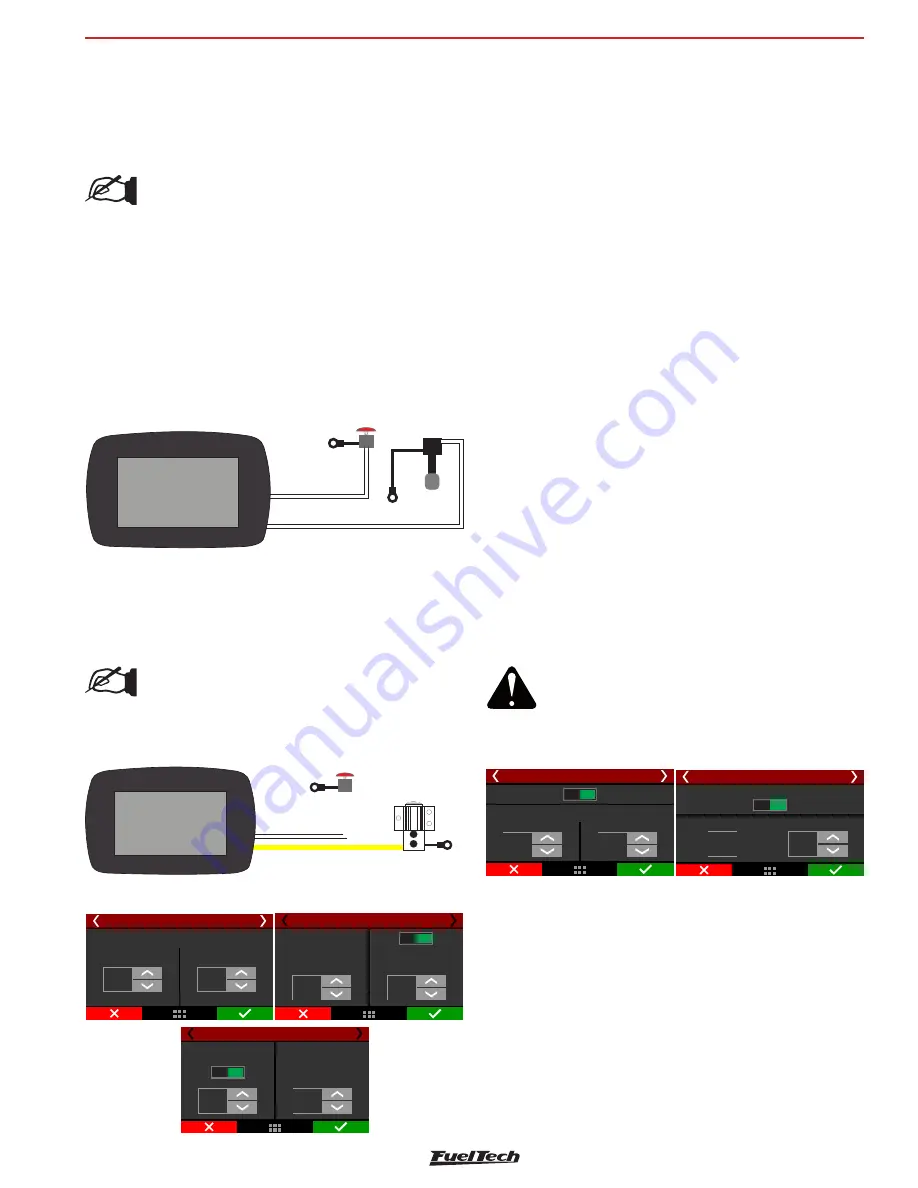
It is possible to set the ignition cut maximum level, that is the percentage
of ignition events cut to keep the engine under the rev limiter.
The RPM progression range acts as a smoothing for ignition cut.
Example: rev limiter at 8000rpm, RPM progression range at 200rpm.
From 8000rpm the ignition cut level will gradually increase until it
reaches 90% cut at 8200rpm.
Percentages less than 90% may not keep the engine under the rev
limiter. Bigger RPM progression range tend to stabilize more smoothly
the rev limiter, but allows the RPM to pass the RPM set as rev limiter.
These numbers are valid to all kinds of ignition cut, with the exception
of time based compensations (time based RPM and driveshaft RPM/
wheel speed) and 2-step. These features have their own parameters.
For inductive ignition systems it is recommended to use 90% maximum
level and 200 RPM progression range. For capacitive system, like
MSD, it is recommended to use 100% maximum level and 1 RPM
progression range.
The parameter “Start compensation X RPM before” is used to start the
timing retard and the fuel enrichment before the RPM for ignition cut.
The minimum TPS to activate timing retard and fuel enrichment allows
the driver to hold the engine in the rev limiter without any compensation
when not needed.
The time based compensations will only work after the realease of a
valid 2-step. This means hold the 2-step button with more then 50%
TPS or reach the rev limiter on time at least.
2-step rev. limiter 7/8
Disabled
Time based
Block 2-step after launch
Duration
7,00
s
When above:
5000
RPM
Actived below
actived above
Actived value
3,51
bar
bar
Actual
3,50
bar
2-step actived value
2-step rev. limiter 8/8
To prevent the driver to activate the 2-step on a run, there are 2
safety parameters. Block 2-step by time or by RPM. This way, even if
th driver press the 2-step button, it will not activate before the time
slip or above the RPM.
When using the 2-step by an input sensor, you must indicate an above
or below value which the 2-step must be considered active.
20.4 Timing table for rev launch
This timing table is only used for burnout mode, 2-step and 3-step. This
is not a compensation table, but a table with absolute timing values,
which ignores any other timing table or compensation.
ATTENTION:
When the 2-step is by wheel speed, its working
can be checked through the first page of
Diagnostic Panel, since it is not being used any
2-step button input.
White wire #2
Button
2-Step
White wire
Clutch Pedal
Clutch
Button
Negative battery
o 12V
r
switched
Negative battery
o 12V
r
switched
Line Lock wiring diagram
To activate the Line Lock, it's recommended to use an yellow output.
The ground can be connected directly to the battery negative or the
chassis/engine block ground.
NOTE:
If the solenoid has a resistance below 4 ohms, it needs
to be powered by a relay.
button, after that, the driver can release the 2-step and the clutch button
will be responsible for the launch, activating all the timed functions
the exact moment the launch occurred. This procedure prevents the
differences between the moment where the clutch and the 2 step
button are released.
NOTE:
- Nothing happens if the clutch button is
activated and the 2-step button is not
pressed.
- The 2-step button will keep functioning
normally, without depending on the clutch
button.
Clutch button wiring diagram
The clutch button must be wired to the white input that has been
setup on the FT. The ground can be connected directly to the battery
negative or the chassis/engine block ground.
Output
Yellow wire
Line Lock
White wire 2
Button
2-Step
Solenoid
Line Lock
Ground
Ground


