FT500 SFI / FT500LITE SFI
70
Other functions
The next screen allows to quickly enable or disable the function and
choose the control mode: by rpm, by time (after 2-step) or by speed.
Generic duty cycle output 4/9
Disabled
Enabled
Programmed value
when
is:
TPS
80,0
%
Progressive output
When this option is enabled,
the output is progressive to
table. Programed value will be
Reached for TPS setup beside.
PWM frequency
15
Hz
Activated at 12V
Activated at 0V
Output Signal
Generic duty cycle output 6 9
/
Generic duty cycle
increase button:
20
%
Disab.
Enab.
Generic duty cycle output 7 9
/
2-step
duty cycle
0
%
“Programmed boost when TPS is over” is the minimum TPS value to
activate the boost solenoid. When the progressive output is selected,
boost output is progressive to boost table, starting at 10% to the
“Programmed boost when TPS is over” value.
•
The recommended frequency for most PWM 3-way valve is 20Hz.
The output signal depends on the solenoid instalation. Check
Chapter 13.8 for further information.
• Select if you want to use the Boost+ button.
The boost duty cycle for 2-step is the boost level when the 2-step is
on, desconsidering any other boost table.
[%]
+
-
3
1
PWM
[%]
100
0
800
600
Revs
[
]
RPM
50
400
2
RPM based boost duty cycle table
Generic duty cycle output 8/9
100
75
50
25
0
400
1500
3000
4500
6000
9000
7500
Generic duty cycle output 9/9
At last, there will be the boost duty cycle table by rpm, speed or time.
The boost by time starts after the 2-step release.
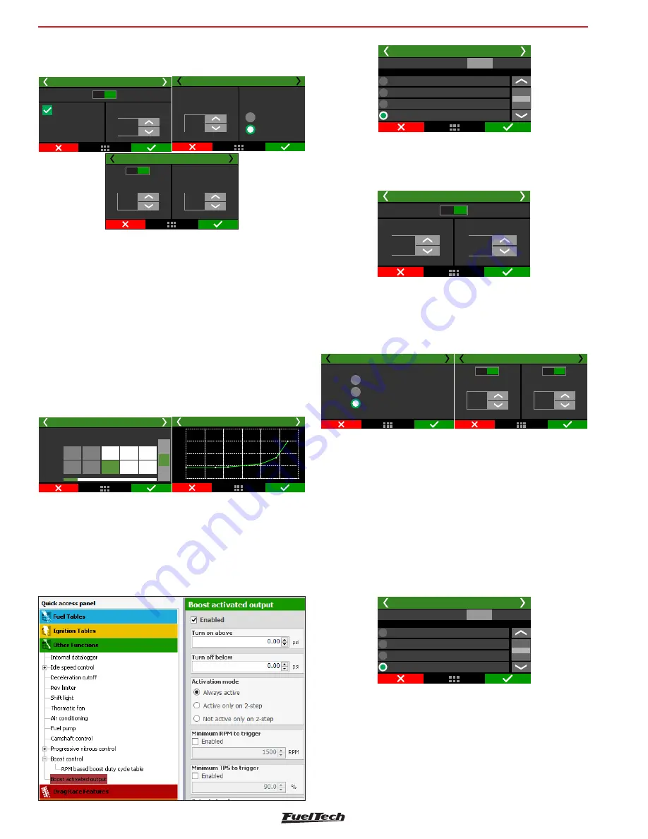
19.12 Boost activated output
This function is used to activate an auxiliary output according to MAP
readings.
Boost activated output 1/2
Yellow 1: Camshaft control
Yellow 2: Progressive nitrous control
Yellow 3: Boost control
Yellow 4: Available
Output selection
Test output:
Test
Select an available output to trigger a relay or any other external device.
In the FTManager, this setup is at “Sensors and calibration” - “Outputs”
Boost activated output 2/2
Turn off below:
1,20
bar
Turn on above:
-0,10
bar
Disabled
Enabled
Select the output signal sent when it is activated. The only outputs
capable of switch 12V are the yellow.
Define the vaccum/boost range to trigger the output.
Boost activated output 4/5
Not active only on 2-step
Active only on 2-step
Always active
Boost activated outputs 5/5
Disab.
Enab.
Minimum TPS to
trigger
90,0
%
Minimum RPM to
trigger
7000
RPM
Disab.
Enab.
There are 3 different activation modes: “always active”, “active only
on 2-step” or “Not active only on 2-step”. This means that even if
the vaccum/boost conditions are met, the activation mode condition
must be respected.
As safety features, minimum TPS and RPM values can be set, so the
output will not activate if one or more conditions are not met.
19.13 Tachometer output
By default, the tach output is configured in the grey #8 wire, but can
be set in the yellow wires also.
Tachometer output
Gray 5: Available
Gray 6: Progressive nitrous control
Gray 7: Boost control
Gray 8: Available
Output selection
Test output:
Test
If one of this outputs are not available, the blue #1 to #8 and grey #1
to #7 can also be used, but an external 12V pull-up with a 1K resistor.
In the FTManager, this setup is at “Sensors and calibration” - “Outputs”


