188
PB
UPDATING VRP FIRMWARE
VRP Remote Upgrade Procedure
Starting Remote Upgrade
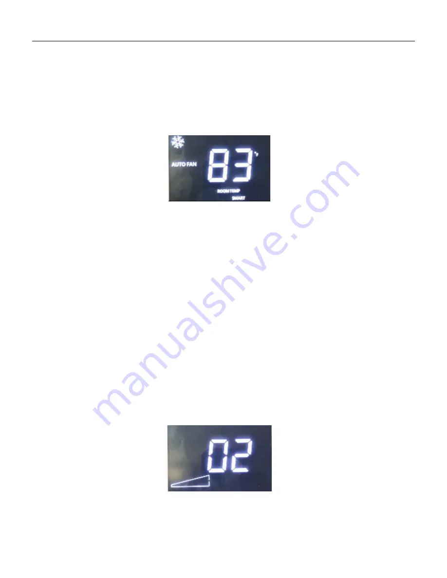
To begin the procedure, ensure that the machine is on and in standby mode with “Smart”
illuminated
All that is required to start the Remote Upgrade procedure is to insert the “Remote Update” SD Card
into the SD Card slot of the Wall Controller. If the system detects that there is no need to upgrade
(all the Software Revisions already match), the Wall Controller will momentarily drop connection to
the FMC (the “Smart” Icon will turn off). After a moment it will recover connection and continue
regular operation.
Tracking Progress
While there is no percentage completion display, there are multiple visual cues to track the
progress of the Remote Upgrade process. The two-digit portion of the screen will show
combinations of numbers and letters to display which stage of the process the system is in, to
display success or failure, or to display an error if one is detected. The update process will take
approximately 20 minutes.
Stage Display
After the card is inserted the WC screen will display a series of letters and numbers. The first to
be displayed is “UP” and the Hourglass Icon. After the system determines that the FMC is OK to
continue the procedure, a “02” will be displayed while the FMC verifies the MCS’s status:
As the procedure progresses, these numbers will change to display each stage of the process.
The highest stage that might be seen is stage 9.
2
Summary of Contents for VRP12K
Page 46: ...46 OPERATION Component Identification Indoor Coil 36k ...
Page 48: ...48 OPERATION Component Identification Outdoor Coil Monitored by 1 thermistor ...
Page 49: ...49 OPERATION Component Identification Outdoor Fan BLDC Variable Speed 600 1000 RPM ...
Page 53: ...53 OPERATION Component Identification 4 Way Reversing Valve 208 230v Reversing valve assembly ...
Page 177: ...177 UPDATING VRP FIRMWARE Or ...
Page 184: ...184 UPDATING VRP FIRMWARE Open zip file Copy to SD Card Insert into SD Card Slot ...
Page 193: ...193 UPDATING VRP FIRMWARE Retrieving VRP Data Remove SD Card from FMC and Locate DF Folder ...
Page 196: ...196 WIRINGDIAGRAMS 12 24K BTU 208 230V 7 5 10 0 KW Figure 801 Wiring Diagram ...
Page 197: ...197 WIRING DIAGRAMS 12 24K BTU 208 230V 2 5 3 4 5 0 KW Figure 802 Wiring Diagram ...
Page 198: ...198 WIRING DIAGRAMS 12 24K BTU 265V 2 5 3 4 5 0 kW Figure 803 Wiring Diagram ...
Page 199: ...199 WIRING DIAGRAMS 12 24K BTU 265V 7 5 10 kW Figure 804 Wiring Diagram ...
Page 200: ...200 WIRING DIAGRAMS 36K BTU 208 230V Figure 805 Wiring Diagram ...


