121
PB
COMPONENT TESTING
Electronic Expansion Valve (EEV)
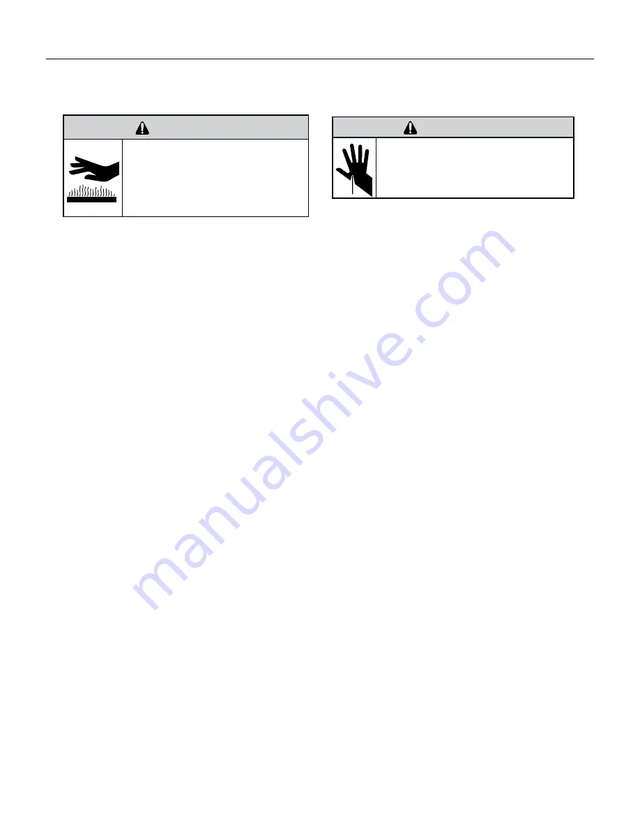
BURN HAZARD
Proper safety procedures must be followed,
and proper protective clothing must be worn
when working with a torch.
Failure to follow these procedures could
result in moderate or serious injury.
WARNING
WARNING
CUT/SEVER HAZARD
Be careful with the sharp edges and corners.
Wear protective clothing and gloves, etc.
Failure to do so could result in serious injury.
All units are equipped with Electronic Expansion Valve (EEV) metering devices.
The electronic expansion valve (EEV) operates with a much more sophisticated design than Capillary tube metering devices.
EEVs control the flow of refrigerant entering a direct expansion evaporator. They do this in response to signals sent to them by
an electronic controller. A small motor is used to open and close the valve port.
Check Stepper Motor
1. To remove the stepper motor from the valve body, rotate the stepper motor approximatately 30 degrees to unlock the locking
tabs, and then lift straight up.
2. Check that the stepper motor is plugged into the FMC (EEV, P13).
3. Verify wires are connected and intact on stepper motor.
4. Check the resistance of the stepper motor by ohming out all of the wires to each other.
5. The resistance of the blue wire to the either the yellow, orange, black, or red wire should be 46 ohms.
6. The resistance of the yellow, orange, black, or red wires to each other should be 93 ohms.
Checking for restrictions
1. Connect pressure gauges to unit.
2. Start the unit in the cooling mode. If after a few minutes of operation the pressures are normal, the EEV is not restricted.
3. Switch the unit to the heating mode and observe the gauge readings after a few minutes running time. If the system
pressure is normal, the EEV is not restricted.
4. If the operating pressures are lower than normal in both the heating and cooling mode, or the system pressure is very high
(over 575psi) on the liquid side and very low (or vacuum) on the low side, the EEV may be restricted.
5. Inspect and examine the EEV stepper motor first! Then Verify the unit has proper refrigerant charge and no leaks prior to
continuing diagnosis of bad Valve body.
Possible causes for expansion valve failures:
1. Initial installation of equipment or a valve replacement. When installing the air handler, evaporator coil case, or an
expansion valve, always protect the sensor (EEV) from the heat of the pipe as you solder in the suction line. Do this by either
wrapping the sensor in cold water or simply remove the sensor from the line before you solder (this is the best way to insure
no damage to the sensor). Many sensors have been damaged on install by not removing them (they are hiding behind the
equipment panel within inches from the suction line stub out). The EEV sensor will usually not fail completely but will be out
of calibration and produce an incorrect temperature reading which results in an incorrect super heat control. The repair on
a brand new unit or replacement valve will cost the hvac company time, money and not to mention major frustration to the
technician and customer. PLUS the customer’s confidence in the technician and the equipment fails too, and that is more
devastating to the company than anything else!
2. Low air flow or turbulent air flow (i.e. short plenum distribution boxes or bull head T fittings. These conditions can cause
the EEV valve to shut down due to a very cold coil and the valve is incorrectly replaced as failed shut.
Summary of Contents for VRP12K
Page 46: ...46 OPERATION Component Identification Indoor Coil 36k ...
Page 48: ...48 OPERATION Component Identification Outdoor Coil Monitored by 1 thermistor ...
Page 49: ...49 OPERATION Component Identification Outdoor Fan BLDC Variable Speed 600 1000 RPM ...
Page 53: ...53 OPERATION Component Identification 4 Way Reversing Valve 208 230v Reversing valve assembly ...
Page 177: ...177 UPDATING VRP FIRMWARE Or ...
Page 184: ...184 UPDATING VRP FIRMWARE Open zip file Copy to SD Card Insert into SD Card Slot ...
Page 193: ...193 UPDATING VRP FIRMWARE Retrieving VRP Data Remove SD Card from FMC and Locate DF Folder ...
Page 196: ...196 WIRINGDIAGRAMS 12 24K BTU 208 230V 7 5 10 0 KW Figure 801 Wiring Diagram ...
Page 197: ...197 WIRING DIAGRAMS 12 24K BTU 208 230V 2 5 3 4 5 0 KW Figure 802 Wiring Diagram ...
Page 198: ...198 WIRING DIAGRAMS 12 24K BTU 265V 2 5 3 4 5 0 kW Figure 803 Wiring Diagram ...
Page 199: ...199 WIRING DIAGRAMS 12 24K BTU 265V 7 5 10 kW Figure 804 Wiring Diagram ...
Page 200: ...200 WIRING DIAGRAMS 36K BTU 208 230V Figure 805 Wiring Diagram ...


