


ATM Controller and AAL0, AAL1, and AAL5
MPC8260 PowerQUICC II Family Reference Manual, Rev. 2
30-88
Freescale Semiconductor
30.13.1 General FCC Mode Register (GFMR)
The GFMR mode field should be programmed for ATM mode. To enable transmit and receive functions,
ENT and ENR must be set as the last step in the initialization process. Full GFMR details are given in
Section 29.2, “General FCC Mode Registers (GFMRx).”
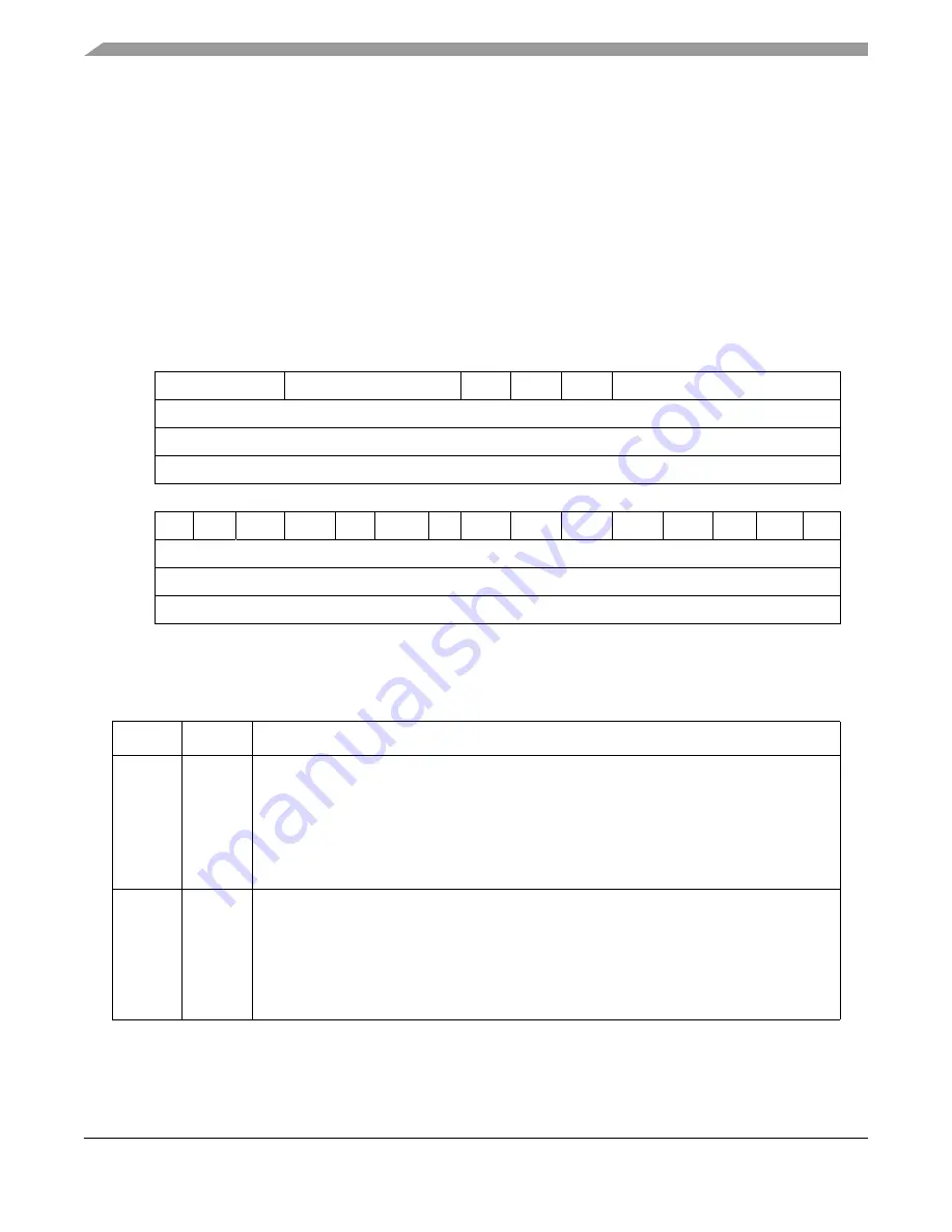
30.13.2 FCC Protocol-Specific Mode Register (FPSMR)
The FCC protocol-specific mode register (FPSMR), shown in
Figure 30-59
, controls various
protocol-specific FCC functions. The user should initialize the FPSMR. Erratic behavior may result if
there is an attempt to write to the FPSMR while the transmitter and receiver are enabled.
Table 30-47
describes FPSMR fields.
0
3
4
7
8
9
10
11
15
Field
TEHS
REHS
ICD
TUMS RUMS
LAST PHY/PHY ID
Reset
0000_0000_0000_0000
R/W
R/W
Addr
0x11304 (FPSMR1), 0x11324 (FPSMR2), 0x11344(FPSMR3)
16 17
18
19
20
21
22
23
24
25
26
27
28
29
30
31
Field
—
TPRI TUDC RUDC RXP
TUMP
—
TSIZE RSIZE UPRM UPLM RUMP HECI HECC COS
Reset
0000_0000_0000_0000
R/W
R/W
Addr
0x11306 (FPSMR1), 0x11326 (FPSMR2), 0x11346 (FPSMR3)
Figure 30-59. FCC ATM Mode Register (FPSMR)
Table 30-47. FCC ATM Mode Register (FPSMR)
Bits
Name Description
0–3
TEHS
Transmit extra header size. Used only in user-defined cell mode to hold the Tx user-defined
cells’ extra header size. Values between 0–11 are valid. TEHS = 0 generates 1 byte of extra
header; TEHS = 11 generates 12 bytes of extra header.
Note:
When working with a 16-bit UTOPIA interface, TEHS must represent an even number of
header bytes (so the actual programmed value should be odd).
Note:
For IMA
1
there is no extra header support for User defined cells so these bits should be
programmed to zero for IMA support.
4–7
REHS
Receive extra header size. Used only in user-defined cell mode to hold the Rx user-defined
cells’ extra header size. Values between 0–11 are valid. For REHS = 0, the receiver expects 1
byte of extra header; for REHS = 11, it expects 12 bytes of extra header.
Note: When working with a 16-bit UTOPIA interface, REHS must represent an even number of
header bytes (so the actual programmed value should be odd).
Note:
For IMA
1
there is no extra header support for User defined cells so these bits should be
programmed to zero for IMA support.
Summary of Contents for MPC8250
Page 90: ...MPC8260 PowerQUICC II Family Reference Manual Rev 2 lxxxviii Freescale Semiconductor...
Page 94: ...MPC8260 PowerQUICC II Family Reference Manual Rev 2 I 4 Freescale Semiconductor...
Page 118: ...Overview MPC8260 PowerQUICC II Family Reference Manual Rev 2 1 24 Freescale Semiconductor...
Page 236: ...Reset MPC8260 PowerQUICC II Family Reference Manual Rev 2 5 14 Freescale Semiconductor...
Page 274: ...60x Signals MPC8260 PowerQUICC II Family Reference Manual Rev 2 7 18 Freescale Semiconductor...
Page 548: ...MPC8260 PowerQUICC II Family Reference Manual Rev 2 IV 8 Freescale Semiconductor...
Page 1072: ...ATM AAL2 MPC8260 PowerQUICC II Family Reference Manual Rev 2 32 10 Freescale Semiconductor...
Page 1356: ...MPC8260 PowerQUICC II Family Reference Manual Rev 2 Index 28 Freescale Semiconductor U U Index...