


ATM Controller and AAL0, AAL1, and AAL5
MPC8260 PowerQUICC II Family Reference Manual, Rev. 2
30-86
Freescale Semiconductor
30.12.2 UTOPIA Interface Slave Mode
In UTOPIA slave mode (single or multiple PHY), cells are transferred using cell-level and octet-level
handshakes as defined by the UTOPIA level-2 standard. The FCC allows cell transfer to be halted or
paused. If the master negates TXENB, the cell that the FCC is transmitting is halted. If the master negates
RXENB, the cell that the FCC is receiving is paused. Note the following restriction on halting a cell
transfer: there cannot be a halt immediately before the transfer of the last data word. There is no restriction
on pausing a cell transfer.
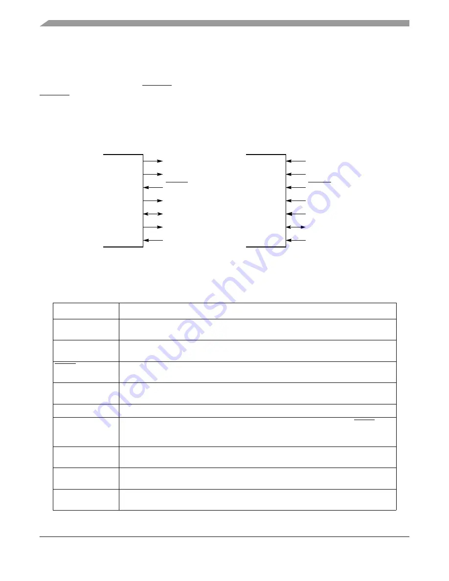
UTOPIA slave signals are shown in
Figure 30-58
.
Figure 30-58. UTOPIA Slave Mode Signals
Table 30-45
describes UTOPIA slave mode signals.
Table 30-45. UTOPIA Slave Mode Signals
Signal
Description
TxDATA[15–0]/[7–0]
Transmit data bus. Carries transmit data from the ATM controller to the master device.
TxDATA[15]/[7] is the msb, TxDATA[0] is the lsb.
TxSOC
Transmit start of cell. Asserted by an ATM controller as the first byte of a cell is sent on the
TxDATA lines.
TxENB
Transmit enable. An input to the ATM controller. It is asserted by the UTOPIA master to signal
the slave to send data in the next TxCLK cycle.
TxCLAV
Transmit cell available. Asserted by the ATM controller to indicate it has a complete cell to
transmit.
TxPRTY
Transmit parity. Asserted by the ATM controller. It is an odd parity bit over the TxDATA.
TxCLK
Transmit clock. Provides the synchronization reference for the TxDATA, TxSOC, TxENB,
TxCLAV, and TxPRTY signals. All of the above signals are sampled at low-to-high transitions of
TxCLK.
TxADD[4–0]
Transmit address. Address bus from the master to the ATM controller used to select the
appropriate M-PHY device.
RxDATA[15–0]/[7–0]
Receive data bus. Carries receive data from the master to the ATM controller. RxDATA[15]/[7]
is the msb, RxDATA[0] is the lsb.
RxSOC
Receive start of cell. Asserted by the master device whenever the first byte of a cell is being
received on the RxDATA lines.
TXDATA[15–0]/[7–0]
TXSOC
TXENB
TXPRTY
TXCLK
TXCLAV
TXADD[4–0]
PowerQUICC II
RXDATA[15–0]/[7–0]
RXSOC
RXENB
RXPRTY
RXCLK
RXCLAV
RXADD[4–0]
PowerQUICC II
Summary of Contents for MPC8250
Page 90: ...MPC8260 PowerQUICC II Family Reference Manual Rev 2 lxxxviii Freescale Semiconductor...
Page 94: ...MPC8260 PowerQUICC II Family Reference Manual Rev 2 I 4 Freescale Semiconductor...
Page 118: ...Overview MPC8260 PowerQUICC II Family Reference Manual Rev 2 1 24 Freescale Semiconductor...
Page 236: ...Reset MPC8260 PowerQUICC II Family Reference Manual Rev 2 5 14 Freescale Semiconductor...
Page 274: ...60x Signals MPC8260 PowerQUICC II Family Reference Manual Rev 2 7 18 Freescale Semiconductor...
Page 548: ...MPC8260 PowerQUICC II Family Reference Manual Rev 2 IV 8 Freescale Semiconductor...
Page 1072: ...ATM AAL2 MPC8260 PowerQUICC II Family Reference Manual Rev 2 32 10 Freescale Semiconductor...
Page 1356: ...MPC8260 PowerQUICC II Family Reference Manual Rev 2 Index 28 Freescale Semiconductor U U Index...


