


57
Setup Settings
1) Connect and assign video signals as shown in the figure above.
2) Device Setup on the MFR-5000:
Connect to the MFR-5000 from the Web-based Control PC and open the [
Tally System
Settings - Device Select
] page. Select
HVS-390HS
in the [
Switcher
] field and click
[
Send
].
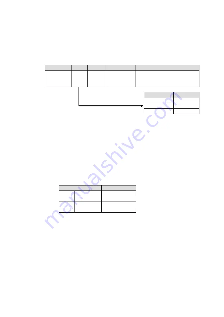
3) Network settings on the MFR-5000:
Open the [
Router System Settings - PortSettings
] page and set the TCP/IP menu as
shown below.
IP Address
Port
Protocol
Function
Local Port(MFR)
(Switcher's
IP address)
※
UDP
Editor(HVS)
Select a UDP port number.
Do not use the UDP port number
(Default: 23) already used in the
Server (MFR).
4) Assign AUX buses and input channels on the switcher to logical destination and sources
channels on the MFR-5000.
<AUX bus assignments>
a) Open the
Destination Assignment
page.
b) Select
HVS(AUX)
under
Select Table
.
c) Set
Level
to
1
.
d) Assign
AUX1
to
DST 129
.
<Input channel assignments>
a) Open the
Source Assignment
page.
b) Select
HVS(AUX)
under
Select Table
.
c) Set
Level
to
1
.
d) Assign input channels to MFR sources as shown below.
LogicalNo./Name
Switcher Channel
129
SRC 129
IN1
|
|
|
136
SRC 136
IN8
137
SRC 137
STL3
5) Settings on the switcher:
Open the [SETUP - EXT I/F - EDITOR] menu on the HVS-390HS.
Change [TYPE] to [
DVS
] and [ENABLE] to [
ON
].
After above setup settings are complete:
If
SRC 129
is selected for
DST 129
,
AUX1
outputs
IN1
video on the switcher.
If
SRC 137
is selected for
DST 129
,
AUX1
outputs
Still 3
video on the switcher.
If
IN4
is selected for
AUX1
on the switcher,
SRC 132
is selected for
DST 129
on the MFR-5000.
Switcher
Port
HVS-390HS
8740
HVS-100/110
8740
HVS-2000
53381


