


50
Note that in all MFR-5000 units the IP address of MFR-LAN1 is set to 192.168.1.10
and that of PC-LAN to 192.168.1.12 as factory default. To prevent IP address overlap
in a system, you need to change IP addresses of either unit.
Also note that desired IP addresses can be set for system devices according to your
network conditions.
Setup Procedure
1) Connect all devices in the MFR system as shown in the figure in the previous page.
Power on the MFR-5000 to be set as a Master, Remote Control unit and PC. Set the IP
addresses for the Remote Control unit (
①
) and PC (
④
). Power off the MFR-5000.
2) Power on another MFR-5000. Set the IP addresses (
⑤
and
⑥
) as shown in the
previous page.
3) Power on the Master MFR-5000.
4) Connect to the Master MFR-5000 Web-based control and open the
Build Settings
page. Check on
Build Enable
to enable the Main Unit Link feature.
See section 11 "Main Unit Link" in the "Web-based Control Operation Manual."
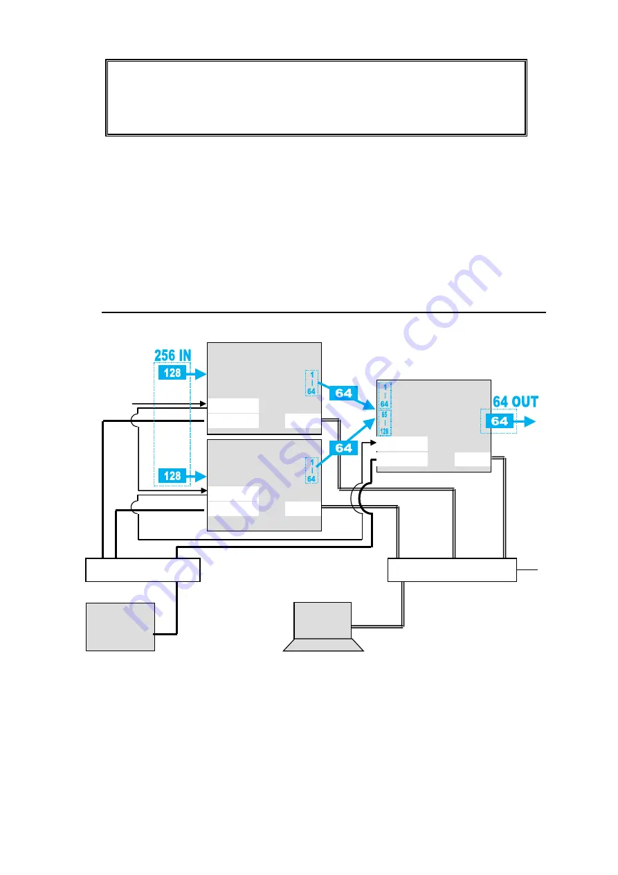
3-2-2. Expanded Matrix System Example
The system example below connects three MFR-5000 units to form a 256 x 64 virtual matrix.
Setup Procedure
1) Connect three MFR-5000 units, one by one, to the MFR system, referring to the
previous chapter for details on to setting network settings. Do not use the same IP
address twice in the system.
2) Connect all three MFR-5000 units to the MFR system. Connect BNC cables based on
SDI signal routing paths.
3) Connect to the Web-based Control of an MFR-5000 and open the
Build Settings
page. Check on
Build Enable
to enable the Main Unit Link feature.
See section 11 "Main Unit Link" in the "Web-based Control Operation Manual."
Ethernet Hub (MFR-LAN)
MFR-xxRU
PC
MFR Web-based
Control
BB
MFR-LAN
PC-LAN
REF IN
MFR-5000
MFR-LAN
PC-LAN
REF IN
MFR-5000
(Master)
MFR-LAN
PC-LAN
REF IN
MFR-5000
Ethernet Hub (PC-LAN)


