background image

23


7-2. How to Assign Sources to Bus buttons 

Primary and optional video inputs, internally generated signals (black, mattes etc) and captured 
stills can be freely be assigned to any PGM/PST or KEY/AUX bus buttons using the procedure 
below. 


(1) Press the MENU button and then press the 7/SETUP button to display the SETUP menu’s 

top page. 

(2) Turn F1 to select INPUT. Press F1 or the PAGE DOWN button to display the  [SETUP – 

INPUT] menu. 


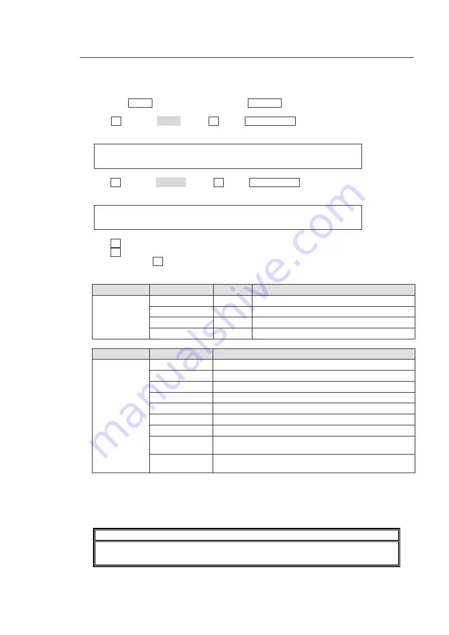
SETUP   :>SIGNAL  >PROC AMP>RENAME  >ASSIGN    
INPUT   :                                      

 
(3) Turn F1 to select ASSIGN. Press F1 or the PAGE DOWN button to display the [SETUP – 

INPUT - ASSIGN] menu. 


INPUT   :BUTTON : SIGNAL NAME   :INHIBIT: 1/3  
OUASSIGN: =01   : =IN04   =CAM4 : =ON   :      


(4) Turn F1 to select a bus button under the 

BUTTON

 item. 

(5) Turn F2 to select the signal to be assigned under the 

SIGNAL

 item. Users can also select a 

signal by turning F3 under the 

NAME

  item.  

SIGNAL

 and 

NAME

 are linked to each other. 

(See section 7-1. "How to Give Name to Source” for more details.) 


Submenu 

Parameter 

Default 

Setting range 

BUTTON 1  1-12, sft1-sft12 (shifted buttons) 
SIGNAL 01 

(See the table below)  

NAME IN01 

(Signal name set in SETUP-INPUT menu) 

ASSIGN 

INHBIT OFF 

OFF, ON 


BUTTON 

SIGNAL setting 

Description 

NONE 

No signal assignment 

BLACK Black 

signal 

IN01

IN04 

Video input to rear connectors 1-4 

STIL1, STIL2 

Still pictures 1 and 2 

MATT 

BUS MATT Color 

CLBAR 

Internally generated color bar signal 

SHIFT 

Shift button function 

INA1-INA4 

Optional video input to rear connectors of slot A (See 

section 2-3.) (*1) 

01 to 12, 
sft01 to sft12 

(shifted buttons) 

INB1-INB4 

Optional video input to rear connectors of slot B (See 

section 2-3.) (*1) 

(*1) IN05-12 are the same video as INA1-4 and INB1-4. 


(6) Users can inhibit specific bus buttons.  If  INHIBIT is set to ON for a bus button, the selected 

bus button for the PGM/PST cannot be selected. This is useful to help reduce the risk of 
wrong input selection.  


IMPORTANT 

The INHIBIT setting has no effect for the KEY/AUX bus.


Even if a bus button cannot be 

used with the PGM/PST, it can be used for the key source, key insert or AUX output.

Summary of Contents for HVS-300HS

Page 1: ...HVS 300HS Digital Video Switcher HVS 30OU Operation Unit 1st Edition Rev 1 OPERATION MANUAL...

Page 2: ...Edition Revision History Edit Rev Date Description Where Preliminary 2009 02 13 1 2009 02 27 1 1 2009 03 10 How to back up settings OSD operation added Factual errors corrected 5 4 21 3...

Page 3: ...nsure power cord is firmly plugged into AC outlet Operation Do not operate unit in hazardous or potentially explosive atmospheres Doing so could result in fire explosion or other dangerous results Do...

Page 4: ...and disconnect power cord to avoid potentially hazardous conditions If problems similar to above occur contact authorized service representative before attempting to again operate unit Rack Mount Bra...

Page 5: ...ard Max 2 cards HVS 30ED 1 Editor control option software option 1 Up to two input cards of HVS 30HSDI HSAI PCIN can be installed 2 Up to two output cards of HVS 30HSDO HSAO PCO can be installed HVS 3...

Page 6: ...hipment If damage has occurred or items are missing inform your supplier immediately Rack Mounting The product can be mounted to EIA standard rack units When rack mounting a unit remove the rubber fee...

Page 7: ...u Access Buttons 13 5 1 3 USER Button Menu Shortcut 13 5 2 How to Set Values 14 5 2 1 Displaying Parameters 14 5 2 2 Changing Settings or Values by Using F1 to F4 15 5 2 3 Changing Settings or Values...

Page 8: ...5 KEYER Transitions 35 10 6 Background Transitions 37 10 7 Pattern WIPE Transitions 38 10 8 Advanced Settings for Transitions 39 10 8 1 Fader Limit 39 10 8 2 Transition Rate 40 10 8 3 User Transitions...

Page 9: ...Stills 66 15 Picture in Picture 67 15 1 Setting up PinP 67 15 1 1 Selecting Video for PinP 67 15 1 2 Inserting PinP1 PinP2 Video 67 15 1 3 Position and Size 68 15 1 4 Crop and Border 69 15 2 IN OUT Ef...

Page 10: ...3 Adjusting Video Signal Levels 84 19 3 1 Proc Amp 84 19 3 2 Gamut Clip 84 19 4 Safety Area Markers 85 19 5 Setting Date and Time 86 19 6 Buzzer Brightness and Screen Saver 86 20 Reboot and Initialize...

Page 11: ...uilt in 16 split multiviewer supporting 4 10 or 16 way split views with tally and title display Dual Picture in Picture function Up stream Keyer and DSK both with 2D DVE and advanced Chroma Key Variou...

Page 12: ...n D sub female 2 4 3 5 LAN Used for 10BASE T 100BASE TX Ethernet connection RJ 45 6 EDITOR Used for editor connection 9 pin D sub female 12 4 1 7 GENLOCK Used to input output a genlock signal tri leve...

Page 13: ...preview next transition 8 2 1 8 BUS SELECT Block Used to select a bus Then select a video in the KEY AUX bus No 9 9 KEY AUX Bus Used to select a video signal for the bus selected at the BUS SELECT bl...

Page 14: ...MU Used for HVS 300HS Main Unit connection 2 CONTROL Used for service purposes Do not use 3 DC 12V IN Used for DC power connection from the supplied AC adapter 4 POWER Used for the unit power On Off...

Page 15: ...lled in slot C and D Option Slot Available card Available Video Signal Connector Number of input output per card Refer to HVS 30HSDI HD SD SDI BNC 4 inputs HVS 30HSAI HD SD analog component or HD SD a...

Page 16: ...Signal ground 7 T Out Transmit data 8 R In Receive data 9 FG Frame ground 2 4 2 RS 422 Connector Pin Assignment Table Pin No Signal Name In Out Description 1 FG Frame ground 2 R In Receive data 3 T Ou...

Page 17: ...ng 9 IN09 RED TALLY default setting 10 IN10 RED TALLY default setting 11 IN11 RED TALLY default setting 12 IN12 RED TALLY default setting 13 Signal ground 14 Signal ground 15 Signal ground The pin ass...

Page 18: ...40V 50 60Hz IN OPTION SLOT A B D C S No LAN 10 100BASE T GENLOCK OFF POWER ON CONTROL TO MU S No LABEL DC12V IN 75 ohm termination 75 ohm termination To other device PGM1 TSG REF signal VTR Video Serv...

Page 19: ...NTROL TO MU S No LABEL DC12V IN PC Editor VTR Video Server etc GPI Controller Preview AUX1 AUX Control box AUX Control box ARCNET BNC HD SD SDI HD SD SDI HD SD SDI HD SD SDI HD SD SDI ARCNET ETHERNET...

Page 20: ...play should be flashing at power ON 2 Press the MENU button and then press the 7 SETUP button 3 The SETUP menu s top page appears in the menu display Turn F1 to select SYSTEM and then press F1 SETUP S...

Page 21: ...tarting the switcher USB MEMORY NOR REV REV F4 F3 F2 F1 PAGE 1 2 MENU DIRECT PATT EVENT KEY PAD ALARM USER BUTTON DIRECTION 7 SET UP 4 WIPE 1 8 STILL 5 P in P 2 KEYER 9 FILE 6 MATT 3 DSK MENU DIRECT P...

Page 22: ...nges the Keypad to event memory control buttons CLR TRANS RATE This button displays the TRANS menu The transition rate can be changed by entering the number and then pressing ENT STORE on the Keypad K...

Page 23: ...ing twice quickly SET UP OUTPUT CLN PVW menu AUX1 Pressing twice quickly SETUP OUTPUT AUX XPT 1 2 menu AUX2 Pressing twice quickly SETUP OUTPUT AUX XPT 1 2 menu AUX3 Pressing twice quickly SETUP OUTPU...

Page 24: ...ct a submenu to open by turning F1 The INPUT submenu is selected in the example below Then press F1 or the PAGE DOWN button to the right to open the selected submenu SETUP SYSTEM INPUT OUTPUT PANEL ME...

Page 25: ...ters appear in the display window data is displayed over 2 lines A maximum of four parameters can be displayed at a time The or in front of value indicates that it is possible to change a parameter se...

Page 26: ...the keypad and press ENT STORE MATT BUS MATT COLOR RECALL 1 1 COLOR S 50 0 L 80 2 H 125 5 GREEN IMPORTANT When pressing a push button press it down lightly and release it within 1 sec Note that if you...

Page 27: ...UE DSK EDGE EDGE COLOR SAT LUM HUE INC SRC MATT COLOR SAT LUM HUE EDGE EDGE COLOR SAT LUM HUE KEYER CK KEYER AUTO CK POS X POS Y SELECT BORDER BORDER COLOR SAT LUM HUE WIPE POS ANGL POSITION ANGLE POS...

Page 28: ...e parameters Menu where INIT included Menus to be returned to default settings SETUP SYSTEM menu All SETUP SYSTEM menus WIPE menu s top page All WIPE menus KEYER SETUP menu All KEYER menus DSK SETUP m...

Page 29: ...s displayed SETUP UTILITY TRS CTRL KEY CTRL USER BTN PANEL 4 Turn F1 to select a USER button for use The selected USER button blinks 5 Select MENU or the function type in the TYPE item PANEL SELECT TY...

Page 30: ...ssignable Functions When MARKR Marker was selected for the TYPE item Setting Function Button Indication PGM ENABLE PVW ENABLE CLN ENABLE AUX1 ENABLE AUX2 ENABLE SLOT C CH1 CH2 SLOT D CH1 CH2 Pressing...

Page 31: ...T PinP2 SLIDE TOP PinP2 SLIDE BOTTOM Performs the user transition for PinP2 On Air Lit orange Off Air Unlit When KEYER or DSK was selected for the TYPE item Setting Function Button Indication 2D DVE E...

Page 32: ...al 01 to 04 IN01 to IN04 INPUT01 to INPUT04 SDI video input to rear connectors 1 4 STILL1 STILL2 STL1 STL 2 STILL1 STILL2 Still images 1 and 2 MATT MATT MATTE BUS matte color CLBAR CB COLOR BAR Color...

Page 33: ...o Source for more details Submenu Parameter Default Setting range BUTTON 1 1 12 sft1 sft12 shifted buttons SIGNAL 01 See the table below NAME IN01 Signal name set in SETUP INPUT menu ASSIGN INHBIT OFF...

Page 34: ...Turn F2 to set SDSDI for FORMAT 6 Turn F3 to select an aspect ratio under the RESIZE item INPUT SELECT FORMAT RESIZE FS 1 1 SIGNAL IN04 SDSDI 4 3 ON IMPORTANT The Resize function is automatically enab...

Page 35: ...s Then press F4 to apply the setting WHITE YELLOW CYAN GREEN MAGENTA RED BLUE and BLACK If you want to adjust the selected color or set the color by entering its HSL values turn F1 F2 and F3 to adjust...

Page 36: ...NCI 1 2 AUX XPT AUX1 BLACK OFF OFF 8 1 1 Selecting Video in KEY AUX 1 Press a button in the BUS SELECT section to select an AUX output 2 Press a button in the KEY AUX bus section to select a signal fo...

Page 37: ...explained below 8 2 1 Preview bus monitoring Follow the procedure below to assign the preview video to an AUX output AUX1 is used in the example below 1 Open the SETUP OUTPUT AUX XPT menu referring s...

Page 38: ...itcher can output the CLEAN via an auxiliary output Users can also add the KEYER image to CLEAN To do so proceed as follows 8 3 1 Outputting Clean Image Follow the procedure below to assign the clean...

Page 39: ...gnal mixed with KEYER and DSK 8 5 Setting Up Optional Outputs Two output expansion cards can be installed in slot C and D Option Slot Available card Available Video Signal Connector Number of output p...

Page 40: ...0 50 Ch2 SDSDI 4 3 SQUEEZE LETTER SD Ch1 Ch2 If HVS 30HSAO is installed System format Channel FORMAT setting ASPECT setting Ch1 HDComponent HDComponent HD Ch2 SDComponent Composite 4 3 SQUEEZE LETTER...

Page 41: ...indicate the signal status Lit color Description Red Indicates on air Orange Indicates next output 9 2 PGM PST Switching Mode Users can change the switching mode for the PGM PST bus from P P to A B I...

Page 42: ...HIFT under the SIGNAL item INPUT BUTTON SIGNAL NAME INHIBIT 1 3 OUASSIGN 12 SHIFT CAM4 ON Using the SHIFT function Once the SHIFT function has been assigned to a bus button the SHIFT button works in n...

Page 43: ...use 4 For selecting transition type 5 The AUTO transition button for BKGD and KEYER 6 The CUT transition button for BKGD and KEYER 7 The fader lever for BKGD and KEYER 8 The Auto User transition butt...

Page 44: ...on WIPE Available NOR REV Fader lever KEYER USER TRANS Available ON AIR KEYER button CUT PinP AUTO button Advanced Transition mode MIX Available PinP AUTO button PinP USER TRANS Available ON AIR DSK b...

Page 45: ...ator The DSK ON AIR button can work in different ways such as CUT Scale Up Down or Slide In Out depending on the menu setting See section 10 8 3 User Transitions On air Off air Indication The On Air D...

Page 46: ...9 How to Select Patterns 5 Press AUTO or KEYER AUTO or move the fader lever to perform the KEYER WIPE transition See section 10 7 Pattern WIPE Transitions for the WIPE transition details See section 1...

Page 47: ...E transition See section 10 7 Pattern WIPE Transitions for the WIPE transition details See section 10 8 2 Transition Rate for the transition rate See section 10 8 1 Fader Limit for the fader limit To...

Page 48: ...hange the start position and so on See section 10 9 How to Modify Pattern 6 Set the transition direction by using the direction buttons NOR REV and REVERSE Transition direction RON REV button REV butt...

Page 49: ...ANS RATE LIMIT PATTERN 1 6 BKGD 30 100 0 20 2 Turn F2 to change the value of LIMIT The default setting is 100 0 With this setting the transition is complete with pictures switching fully 3 Verify that...

Page 50: ...the following menu pages Use PAGE UP and PAGE OWN buttons to move between the menu pages The setting range is 0 to 999 on a frame basis TRANS RATE LIMIT PATTERN 1 6 BKGD 30 100 0 20 TRANS RATE USER TR...

Page 51: ...ion for the bus SCALER Performs Scale Up and Down for the bus SLIDE RIGHT LEFT SLIDE TOP BOTTOM Performs Slide In and Out for the bus WIPE RIGHT LEFT USER TRANS WIPE TOP BOTTOM Performs WIPE In and Ou...

Page 52: ...PATTERN 1 6 BKGD 30 100 0 20 2 To change the pattern turn F3 or F4 to select a desired pattern 10 9 2 Direct Pattern Function The Direct Pattern Selection feature uses the number buttons on the keypa...

Page 53: ...ber button where the desired pattern has been saved The transition type is automatically switched to WIPE and the current pattern is changed to the new one To perform quick pattern selections without...

Page 54: ...ern modify some modification data set for the specified pattern may be preserved and applied to the newly selected pattern In this case if you wish the modified pattern to the default settings reset t...

Page 55: ...POS ANGL MULTI SUB EFF No 020 INIT 7 The WIPE BORDER menu appears Turn F1 to select the signal used for the border under the SIGNAL item Select MATT in this example Set the border width under the WIDT...

Page 56: ...display the WIPE menu 6 Turn F1 to select BORDER Press F1 or the PAGE DOWN button WIPE BORDER POS ASP CROP SUB EFF No 1XX INIT 7 The WIPE BORDER menu appears To use the inside border set the border w...

Page 57: ...0 0 0 WIPE BORDER COLOR RECALL 2 2 BORDER S 66 3 L 5 4 H 3 5 BLUE WIPE POSITION ANGLE ASPECT 1 1 POS ANGL X 0 Y 0 0 0 0 0 WIPE MULTI 1 1 MULTI X 1 Y 1 WIPE EFFECT MONO COLOR 1 3 SUB EFF NOR S 0 0 H 0...

Page 58: ...PE BORDER COLOR RECALL 3 3 BDR COL S 66 3 L 5 4 H 3 5 BLUE WIPE POSITION SIZE 1 2 POS SIZE X 0 Y 0 1000 WIPE ASPECT FADE 2 2 ASPECT X 1000 Y 1000 0 0 WIPE CROP POSITION 1 1 CROP T 0 0 B 0 0 L 0 0 R 0...

Page 59: ...RDER COLOR RECALL 3 3 BDR COL S 66 3 L 5 4 H 3 5 BLUE WIPE LIGHTING DIR RAD 1 2 WARP W 0 0 En OFF 0 0 WIPE LIGHT COLOR RECALL 2 2 LIGHTCOL S 0 0 L 100 0 H 0 0 WHITE WIPE CROP POSITION 1 1 CROP T 0 0 B...

Page 60: ...5 4 No 200 WIPE SUB EFF INIT No 2XX WIPE EFFECT MONO COLOR 1 3 SUB EFF NOR S 0 0 H 0 0 En OFF WIPE DEFOCUS PAINT 2 3 SUB EFF H 0 0 V 0 0 Y 0 C 0 WIPE FREEZE STROBE NEGA MOSAIC 3 3 SUB EFF OFF OFF OFF...

Page 61: ...scribes how to set a Luminance key for a DSK 1 Press the DSK or KEYER button in BUS SELECT 2 Select a signal for Key Insert in the KEY AUX bus 3 Double click DSK in BUS SELECT to display the DSK menu...

Page 62: ...INVERT 1 3 INS SRC BUS IN01 IN02 OFF See sections 10 4 DSK Transitions 10 8 3 User Transitions and 10 8 4 Advanced Auto Transitions for details on transitions See section 12 5 Adjusting Key Signal fo...

Page 63: ...Insert signal IN01 Assumed that IN01 is assigned to the source button 1 Source signal IN02 Assumed that IN02 is assigned to the source button 2 Changing to Keyer type BUS Insert signal MATT Assumed th...

Page 64: ...menu is displayed Turn F1 to set TYPE to CHR KEYER TYPE INSERT SOURCE INVERT 1 3 INS SRC CHR IN01 IN01 OFF 6 Press the PAGE UP button to return to the KEYER SETUP menu Turn F1 to select CK and press F...

Page 65: ...o to PAGE3 of the KEYER menu Turn F3 to make HUE adjustments KEYER GAIN CLIP HUE COL CAN 3 5 CK ADJT 1 0 0 0 0 0 ON Chroma Angle The ANGLE parameter determines the width of the color hue Press the PAG...

Page 66: ...different color turn F1 F2 and F3 to adjust the color DSK MATT COLOR RECALL 3 3 INS MATT S 67 3 L 15 8 H 257 5 RED Key Links cannot be used for KEY MATT 12 5 Adjusting Key Signal Clip and Gain allows...

Page 67: ...r 2 Double click DSK or KEYER to display the DSK KEYER menu 3 Turn F1 to select MASK and press F1 or the PAGE DOWN button to open the DSK MASK menu 4 Turn F2 to select BOX in PAGE1 in the MASK menu Se...

Page 68: ...K MASK menu 4 Turn F2 to select an AUX bus used for the mask in PAGE1 in the MASK menu Set TYPE to AND or OR If set to AND the area where Key Source and AUX Mask are overlapped is used as the key sign...

Page 69: ...o set 2D DVE in the menu to ON DSK POSITION SIZE 2D DVE 1 3 POS SIZE X 0 Y 0 1000 ON The 2D DVE function is enabled for DSK and therefore the POS SIZE BORDER and SUB EFFECT menus in the DSK menu becom...

Page 70: ...oth examples Setting the size allows users to change the size of KEY or DSK images while retaining aspect ratios If the value is 1000 the DSK will be of a full screen size To Change Aspect Ratio 1 Pre...

Page 71: ...DSK image Increasing the value makes the backgound transparent 13 5 CROP CROP allows users to trim the KEY image or DSK image from all four directions The background image then only remains visible i...

Page 72: ...o display outlines without key fill images 2 The item SOFT is for setting softness TRANSP is for transparency and WIDTH is for width of the edges DSK TYPE SOFT TRANSP WIDTH 1 3 EDGE O_LIN 0 0 1 3 Pres...

Page 73: ...values DSK MONO COLOR 1 3 SUB EFF S 0 H 0 En ON 13 7 2 DEFOCUS The DEFOCUS function allows users to add an effect that will blur the output image 1 Go to the DSK SUB EFF menu PAGE2 2 Turn F1 to set t...

Page 74: ...on FREEZE Allows users to set enable the freeze effect function Users can select either frame freeze or field freeze STROBE Allows users to enable strobe effects Increasing the value strengthen the fl...

Page 75: ...lf of the border is set at OUTSIDE X and Y WIPE INSIDE OUTSIDE 2 3 BDR SOFT X 0 Y 0 0 4 Press the PAGE DOWN button to go to PAGE3 Turn F4 to select a color for the border from eight standard colors If...

Page 76: ...F2 to select the capture type from FRAME ODD odd field and EVEN even field then press F2 A beep sound will be heard and the still image will be stored to STILL1 To save the image to STILL2 turn F3 to...

Page 77: ...ect Video in the Menu 1 Press twice quickly the PinP1 or PinP2 button in the BUS SELECT to display the PinP1 PinP2 menu 2 Turn F1 to select video under the XPT item PinP1 XPT BORDER ASPECT 1 4 XPT IN1...

Page 78: ...is set as origin 0 0 in the coordinates The position of PinP is specified by the center of the PinP image You can also change the aspect ratio for the PinP image to 4 3 in the menu when in HD mode POS...

Page 79: ...W 5 S 0 16 9 6 Press the PAGE DOWN button to go to PAGE 2 7 Turn F4 to set the border color to BLUE PinP2 BORDER COLOR RECALL 2 4 BDR COL S 66 3 L 5 4 H 3 5 BLUE 15 2 IN OUT Effects The following butt...

Page 80: ...IR Button Item Setting Description CUT Performs Cut in or CUT out of PinP SCALER Performs Scale Up or Down of PinP SLIDE RIGHT LEFT SLIDE TOP BOTTOM Performs Slide in or Slide out of PinP WIPE RIGHT L...

Page 81: ...using the menus In the following examples AUX2 is selected to be the multiviewer output Using Buttons in BUS SELECT 1 Press the AUX2 button in the BUS SELECT block 2 Press the MV button at the right e...

Page 82: ...formation A color border can be also applied to the split screen to emphasize channel areas 16 4 1 Titles 1 Quickly press twice the MV button in the BUS SELECT block to display the SETUP OUTPUT MV SCR...

Page 83: ...OFF FRAME indicator is ON Here we assume that IN02 is displayed in PGM 16 4 3 Frame Border A color border can be also applied to the split screen to emphasize channel areas 1 Quickly press twice the...

Page 84: ...the menu display The EVENT MEMORY menu is displayed and the Keypad switches to EVENT mode 2 Turn F1 to select an event page in the EVENT MEMORY menu PAGE 0 has Event 0 9 event memories PAGE 1 has Eve...

Page 85: ...n be most quickly recalled However users cannot select the loaded data at recalling events To use the direct recall previously set the DIRECT item to ON in the menu 1 Press the EVENT button at the top...

Page 86: ...LAST item in the EVENT MEMORY menu shows the number of the last recalled event This is useful when checking which event was recalled last 17 3 Overwrite Protection 1 Press the EVENT button at the top...

Page 87: ...ering off the switcher You can however recall the desired panel setup whenever the switcher starts by setting in the SETUP SYSTEM INIT menu as shown in the procedure below 1 Press the MENU button at t...

Page 88: ...all wipe data and all event memory data sys hvs 300 sys System data mem event mem All event memory data jpg JPEG format files standard RGB still1 jpg Still 1 capture video jpg 2 still2 jpg Still 2 cap...

Page 89: ...ent to the flash memory the message SAVE will appear Press F3 again to store the data to the flash memory A beep sound will be heard when the data is saved If the same file exists in the USB flash mem...

Page 90: ...e system data files with all or sys extension because the switcher and the control panel may not be disconnected if loading the different connection settings from the previous 18 4 2 To Download Image...

Page 91: ...ish to delete from the flash memory 4 Turn F3 to select the file to be deleted 5 Turn F2 to select DELETE under the CTRL item and press F2 6 Turn F3 to select ON then press F3 A beep sound will be hea...

Page 92: ...menu SETUP FORMAT REF I O ARCNET ETHERNET SYSTEM TIME INIT REBOOT 4 Turn F1 to select the TV format to be used in the switcher Turn F3 to select the aspect ratio SYSTEM FORMAT ASPECT SW TMNG 1 1 FORM...

Page 93: ...or the PAGE DOWN button to open the SETUP SYSTEM REF IN menu 3 Turn F1 to select a reference signal to be input to the switcher between Black Burst and Tri level Sync SYSTEM TYPE 1 2 REF IN BB 19 2 2...

Page 94: ...DOWN button to go to PAGE 2 7 You can adjust the chrominance level under the Pb Lv item and the Pr Lv item INPUT SELECT Pb Lv Pr Lv ENABLE 2 3 PROC AMP IN04 1 00 1 00 ON 19 3 2 Gamut Clip If source v...

Page 95: ...KER item in the SETUP OUTPUT MARKER menu from BOX and HOOK See the figures in the bottom of the page Then go to PAGE 2 select an aspect ratio and set the marker size OUTPUT SELECT ENABLE MARKER SIDECU...

Page 96: ...y and buttons on the control panel and the volume of the buzzer can be adjusted in the menu You can also set the start time of the screen saver shown on the menu display 1 Press the MENU button then p...

Page 97: ...ess F1 or the PAGE DOWN button to open the SETUP SYSTEM menu 3 Turn F1 to select INIT then press F1 or the PAGE DOWN button to display the SETUP SYSTEM INIT menu SETUP FORMAT REF I O ARCNET ETHERNET S...

Page 98: ...ETUP INPUT ASSIGN menu Press the PAGE DOWN button to go to PAGE2 INPUT BUTTON SIGNAL NAME INHIBIT 3 3 FPASSIGN 01 IN04 CAM4 ON 4 Turn F1 to select a button under the BUTTON item 5 Turn F2 to select th...

Page 99: ...is active 21 3 OSD Operation Pressing both of the control push buttons on the HVS 30FP or HVS 30RU control panel simultaneously displays the menu on the preview screen On Screen Display Pressing the...

Page 100: ...tput Option RGB Resolution SXGA WUXGA R G B 0 7Vp p H V TTL Reference Input BB NTSC 0 429Vp p PAL 0 45Vp p or Tri level sync 0 3Vp p 75 or loopthrough 1ea BNC Reference Output BB NTSC 0 429Vp p PAL 0...

Page 101: ...ifications Backup Device USB memory device Interface EDITOR 9 pin D sub female 1ea GPI IN TALLY 15 pin D sub female 1ea 12 input output Ethernet 10 100Base TX RJ 45 1 ea RS422 9 pin D sub female 1 ea...

Page 102: ...480 6 4 6 32 6 44 t2 3 430 3 6 HVS 300HS GPI IN T ALLY OUT RS 42 2 EDIT OR R EF I N R EF O U T TO O U 4 3 2 1 SDI INP UT AUX 2 AUX 1 P GM 2 PGM 1 SDI OUTPUT AC1 00 24 0V 5 0 6 0Hz IN OPT ION S LOT A B...

Page 103: ...V MV 2 3 4 5 6 7 8 9 10 11 12 1 PGM PST 12 11 10 9 8 7 6 5 4 POSITION 1 2 3 KEYER MENU DIRECTPATT EVENT KEYPAD KEY AUX FADER LIMIT ALARM ONAIR USERBUTTON TRANSPREV DIRECTION NEXTTRANSITION PATTERN RAT...

Page 104: ......

Page 105: ...e correct name as shown in the table above when saving to the USB flash memory 2 When loading a JPEG or TARGA file from the USB flash memory you can select a centered or tiled format as well as a norm...

Page 106: ...8 019 020 021 022 023 024 025 026 027 028 029 030 031 032 033 034 035 036 037 038 039 040 041 042 043 044 045 046 047 048 049 050 051 052 053 054 055 056 057 058 059 060 061 062 063 064 065 066 067 06...

Page 107: ...5D DVE Type 100 101 102 103 104 105 106 107 108 109 110 111 112 113 114 115 116 117 118 119 120 121 122 123 124 125 126 127 128 129 130 131 132 133 134 135 136 137 2 3 3D DVE Type 140 141 142 143 144...

Page 108: ......

Page 109: ...Bus Key 52 Bus Matte 25 Buzzer Brightness and Screen Saver 86 C Changing Position KEYER and DVE 59 Changing Settings or Values by Using F1 to F4 15 Changing Settings or Values by Using the Joystick 1...

Page 110: ...Menu 44 How to Return Settings to Default 18 How to Save Stills 66 How to Select Aux signals 26 How to Select Patterns 42 How to Set Values 14 HVS 300HS Dimensions 92 HVS 300HS Main Unit 2 HVS 300HS S...

Page 111: ...PST Switching Mode 31 Picture in Picture 67 Position and Size PinP 68 Power ON 10 Preset Pattern Groups 44 Preview bus monitoring 27 Preview Set Up 27 Proc Amp 84 R Reboot and Initialize 87 Rebooting...

Page 112: ...oring Events 74 SUB EFFECT KEYER and DVE 63 System Initialization 87 System Setup Settings 82 System Signal Format Selection at the Initial Use 10 T Titles Multiviewer 72 To Download Image Files 80 To...

Page 113: ...n the equipment is operated in a commercial environment This equipment generates uses and can radiate radio frequency energy and if not installed and used in accordance with the instruction manual may...

Page 114: ...FOR A Corporation of Canada 425 Queen Street West Suite 211 Toronto Ontario M5V 2A5 CANADA Phone 1 416 977 0343 Fax 1 416 977 0657 FOR A Latin America the Caribbean 5200 Blue lagoon Drive Suite 760 M...

Reviews: