


NetDAQ
Service Manual
4-32
4.
Click the Done button to exit the volts dc calibration cycle.
5.
If this completes your calibration requirements, click the Close button in the
Instrument Calibration dialog box to return to the NetDAQ Logger for Windows
Main Window. Otherwise, continue to the next calibration function.
VAC Calibration Procedure
4-38.
This procedure uses the calibration feature of NetDAQ Logger for Windows. Complete
the “Calibration Procedure (Semiautomatic)” before using this procedure.
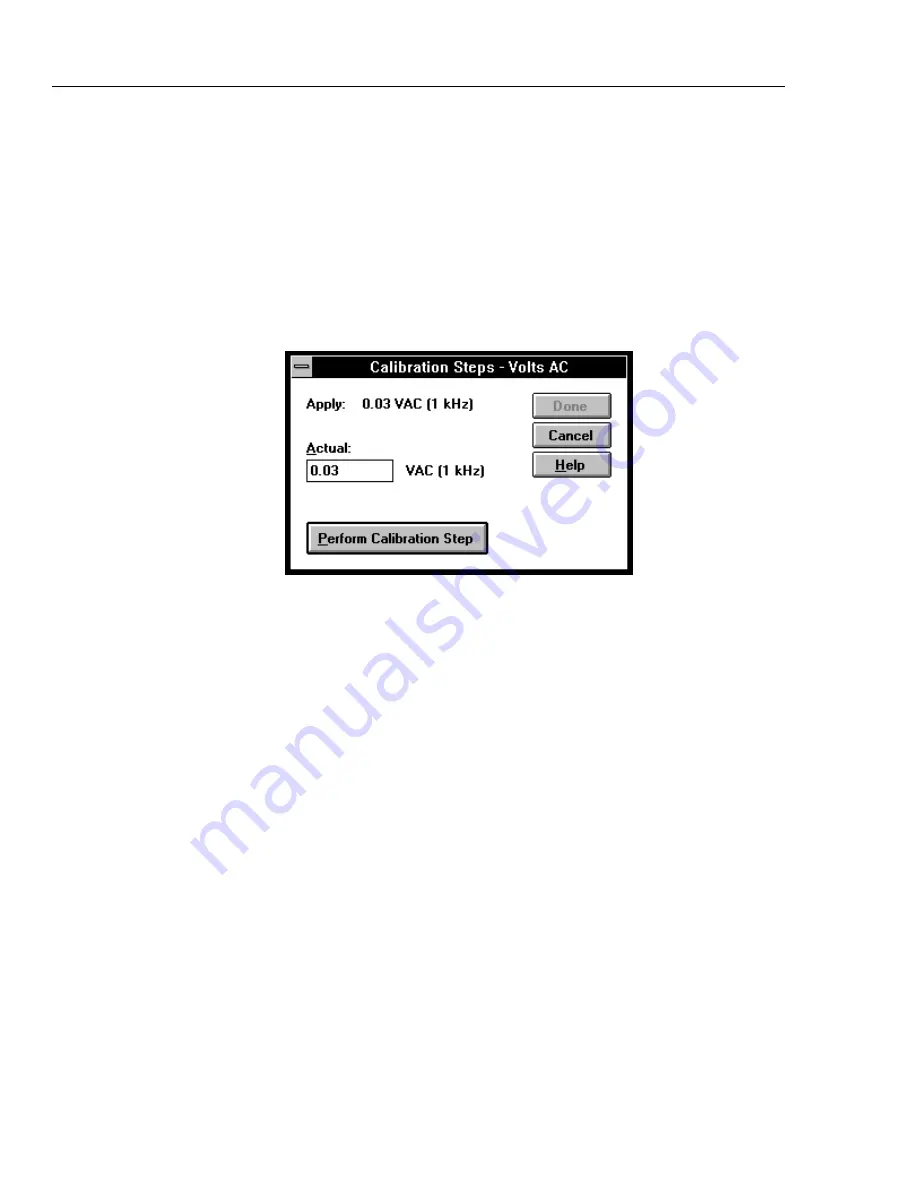
1.
Click the Volts AC button in the Instrument Calibration dialog box, opening the first
Calibration Steps - Volts AC dialog box (below).
If you get an error message, check the RS-232 parameter settings, and cabling, and
make sure no other application such as terminal or internal modem is using the
selected COM port. The error “Calibration Mode not enabled” means you have not
pressed the CAL enable button at the instrument front panel.
2.
Connect the 5700A Calibrator as shown in Figure 4-7 and source an output of 0.03V
ac at a frequency of 1 kHz. Click the Perform Calibration Step button to calibrate the
selected value. After the calibration step completes, the next calibration appears in
the Actual box.
3.
In a similar manner, source the 5700A Calibrator for the values 0.3V, 0.3V, 3V, 3V
(values repeat) and so forth until the Done button is no longer dimmed.
4.
Click the Done button to exit the volts ac calibration cycle.
5.
If this completes your calibration requirements, click the Close button in the
Instrument Calibration dialog box to return to the NetDAQ Logger for Windows
Main Window. Otherwise, continue to the next calibration function.
Summary of Contents for NetDAQ 2640A
Page 14: ...NetDAQ Service Manual x...
Page 46: ...NetDAQ Service Manual 2 4...
Page 106: ...NetDAQ Service Manual 2 64...
Page 108: ...NetDAQ Service Manual 3 2...
Page 164: ...NetDAQ Service Manual 4 42...
Page 206: ...NetDAQ Service Manual 6 2...
Page 218: ...NetDAQ Service Manual 6 14 2645A 1601 Figure 6 2 A1 Main PCA Assembly...
Page 220: ...NetDAQ Service Manual 6 16 2620A 1601 Figure 6 3 A2 Display PCA Assembly...
Page 230: ...NetDAQ Service Manual 6 26 2645A 1603 Figure 6 5 2645A A3 A D Converter PCA Assembly...
Page 234: ...NetDAQ Service Manual 7 2...
Page 242: ...2640A 2645A Service Manual 7 10 Figure 7 2 A2 Display PCA Assembly 2620A 1602...
Page 243: ...Schematic Diagrams 7 7 11 Figure 7 2 A2 Display PCA Assembly cont 2620A 1002...
Page 251: ...Schematic Diagrams 7 7 19 2645A 1603 Figure 7 4 2645A A3 A D Converter PCA Assembly 2645A 1603...
Page 258: ...2640A 2645A Service Manual 7 26 Figure 7 5 A4 Analog Input PCA Assembly 2620A 1604...
Page 260: ...2640A 2645A Service Manual 7 28...


