background image


67 

Enabling the Dispense Instruction Screen 

 
In self-serve applications, you may find it helpful 
to have step-by-step instructions on operating 
the Touchscreen when drawing product.  With 
enabling the Dispense Instruction Screen, the 
operator will go to the “next” screen after 
making the flavor selections.  That screen will 
instruct the operator to draw a serving.  
 
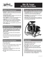
1.  Press the SETUP key in the upper left 

corner.  Enter the password if required.     


2.  Press the MAINTENANCE key.        


3.  Press the SETUP OPTIONS key.  


4.  Press the box next to ENABLE DISPENSE 

INSTRUCTION SCREEN to check the box.  


NOTE:  

TIMED SERVING SIZE AND SELF 

SERVE MODE ARE OPTIONAL FEATURES 
COMPATIBLE WITH THE DISPENSE 
INSTRUCTION SCREEN.  HOWEVER, THEY 
ARE SHOWN UNSELECTED HERE IN THESE 
ILLUSTRATIONS.  ENABLING FCB PURGE IS 
RECOMMENDED. 
 

NOTE:  

“ENABLE INJECTOR FLUSH” IS FOR 

USE WITH NON-FCB SYSTEMS ONLY.  
ENSURE THIS BOX IS 

UNCHECKED.


NOTE:


“ENABLE AUTO DISPENSE MODE” IS 

FOR USE WITH THE FCB AUTO DRAW 
VALVE SYSTEM AND REQUIRES A SPECIAL 
KIT FROM YOUR LOCAL DISTRIBUTOR. 


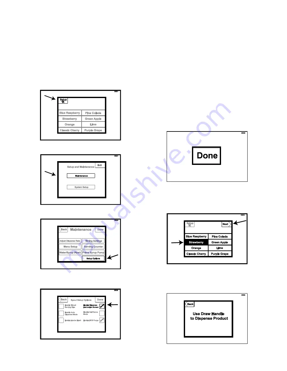
5.  Press the DONE key to return to the main 

screen.    


6.  To test the instruction screen, select the 

flavor(s) and press the NEXT key in the 
upper right corner.   


7.  The next screen will show instructions on 

drawing the product.  After a few moments, 
the screen will default to the main screen.     


Summary of Contents for TS 80FCB

Page 1: ...3528 Fax 317 745 2377 www flavorburst com For pricing ordering and support contact one of our qualified distributors Warranty An installation and warranty form is provided with every FB 80FCB system l...

Page 2: ...eaning Replacing Syrup Port O Rings 29 Miscellaneous Cleaning Procedures 30 Area Under the Cabinet 30 Inside the Cabinet 31 Tube Cable Casing Assembly 31 9 Tube Assembly Syrup Lines 31 Touchscreen and...

Page 3: ...Flavors to the Menu 58 Adjusting Flavor Dispense Rate 59 Adjusting Alternating Flavor Timing 60 Accessing the Water Syrup Flush Mode 61 Accessing the Prime Syrup Pump Mode 62 Enabling the Pass Code F...

Page 4: ...3 PAGE INTENTIONALLY LEFT BLANK...

Page 5: ...the DAILY OPENING PROCEDURES NOTE PARTS AND PART NUMBERS MAY VARY FROM WHAT IS SHOWN AND LISTED CONSULT YOUR LOCAL DISTRIBUTOR IF YOU HAVE ANY QUESTIONS CONCERNING DIFFERENCES Always follow these saf...

Page 6: ...Houses sanitizer cleaning solution 6 SPR 5800FCB SPARE PARTS KIT 1 Houses extra spare parts and wear items 7 N A CABINET ASSEMBLY 1 Houses flavor trays electronics and pumps 8 CAB 113 FLAVOR TRAY 8 Ho...

Page 7: ...6 General System Overview Figure 1...

Page 8: ...s tray support rails 16 CAB 143 LATCH BRACKET 1 Provides latching tab for front panel latch 17 FAS 2001 FRONT DOOR PANEL LATCH 1 Latches front door to cabinet front 18 SYR 927 INTERNAL 9 TUBE ASSEMBLY...

Page 9: ...FAS 2040 6 32 X 1 4 TAPPING SCREW 24 Secures tray support bracket to side panels 34 CAB 135L A LEFT SIDE PANEL 1 Holds tray support brackets and panel brackets 35 SYR 944SH SYRUP TUBE ASSEMBLY SHAKE...

Page 10: ...draw spout from the pumps 5 INJ 117 TUBE CONNECTOR BODY BLACK 1 Secures flavor line manifold to flavor lines 6 MIS 3142 FLAVOR LINE DUST CAP FB 80 1 Covers syrup manifold when not connected 7 INJ 201...

Page 11: ...and tubes of the Casing Assembly 10B MIS 3051 CH 6 CHANNEL MAGNET ASSEMBLY 2 ea Holds the Casing Channel to the freezer panel 10C FAS 2040 6 32 x 1 4 PAN HEAD SCREW 1 ea Secures the Casing cover to th...

Page 12: ...265 BAG COUPLER 1 ea Fastens bag fitment to bag connector 2B TUB 811 TUBE SILICONE 188X 375 PE FB80 1 ea Provides sealed cavity inside bag fitment 2C FIX 1048 FITTING X BARB FB80 1 ea Connects bag cou...

Page 13: ...12 Syrup Pump and Related Parts Figure 4...

Page 14: ...sanitizer pump 12 SAN 701 SANITIZER TANK 1 Holds sanitizer solution 13 MIS 3028 S FLUSH TUBE ASSEMBLY SHAKE 1 Connects with flavor line to flush with sanitizer solution 14 FIX 1023 3 16 X 3 16 BARB TU...

Page 15: ...14 Sanitizer Pump and Related Parts Figure 5...

Page 16: ...Bracket to the freezer 3 ELE 810 SD CARD READER 1 Transfers updated programming and files from the computer to the SD card 4 ELE 434 POWER CABLE 1 Supplies the electronics board with power 5 FAS 2024...

Page 17: ...16 Electronic Parts and Connections Figure 6...

Page 18: ...1 Provides sealed cavity and prevents syrup leakage 4 RUB 660 LARGER SYRUP PORT O RING 1 Provides a sealed cavity inside the syrup port 5 RUB 652 RSS SMALLER SYRUP PORT O RING 1 Provides a sealed cavi...

Page 19: ...ors periodically as desired 1 Mix approved detergent with warm water according to manufacturer s instructions Also prepare approved sanitizer solution according to manufacturer s instructions 2 Place...

Page 20: ...de up As the tray is set back down allow the bag to settle in the tray 11 Make sure the syrup bag is settled neatly into the tray and then install the loaded tray into the cabinet 12 Once the Water Sy...

Page 21: ...bag lock over the adapter and bag fitment 16 Connect the Syrup Bag Connector to the syrup bag fitment 17 Repeat Steps 3 16 for any additional flavors that are being changed out 18 Prime the syrup line...

Page 22: ...ROM THE SPOUT FOR SEVERAL SECONDS AND SERVES NO SPECIFIC PURPOSE WITH THE FCB SYSTEM 22 To prime the syrup line place a container under the spout Press the key of the first flavor and allow the syrup...

Page 23: ...cess must be an approved sanitizing product mixed according to the product manufacturer s instructions This Clean In Place procedure is detailed in three phases 1 9 Tube Assembly Cleaning 2 Syrup Syst...

Page 24: ...izer solution Allow these items to soak throughout the upcoming processes CIP Phase 2 Syrup System Cleaning NOTE THE FOLLOWING CLEAN IN PLACE PROCEDURE STEPS 8 17 SHOULD BE COMPLETED CONSECUTIVELY BEG...

Page 25: ...sh the bag fitment with the Medium Brush and the Connector with the Small Brush Then rinse and dry the parts using clean water and single service towels 14 Using a spray bottle of approved sanitizer s...

Page 26: ...d you to connect the Pump Flush Adapter or Flush Line to the flavor connector which you should have already done in Step 15 It will also show a START STOP key 21 To flush the syrup line press the STAR...

Page 27: ...been sanitized and the syrup have been flushed 26 Return the Pump Flush Adapter to its place under the tray 27 Press DONE to return to the main screen CIP Phase 3 Reassembly 28 Slide a syrup bag lock...

Page 28: ...cure 35 Install the cap on the manifold 36 Prime the syrup system as instructed in the next section Priming the Syrup System Priming the Syrup System Priming the syrups is necessary when first install...

Page 29: ...PENSE FROM THE SPOUT FOR SEVERAL SECONDS AND SERVES NO SPECIFIC PURPOSE WITH THE FCB SYSTEM 5 To prime the syrup line place a container under the spout Press the key of the flavor and allow the syrup...

Page 30: ...CEDURES 4 Reinstall the hand pump and tighten sufficiently Using the handle pump air into the Sanitizer Tank to prime the pump approximately 10 strokes NOTE NO PRESSURE IS NEEDED IN THE TANK DURING NO...

Page 31: ...80FCB do not require daily cleaning Inspect these areas periodically and clean if necessary according to instructions Mix approved detergent with warm water according to manufacturer s instructions A...

Page 32: ...he Tube Casing Assembly from the freezer 2 Using warm detergent water and a single service towel clean the Casing Assembly Disassemble and clean the individual parts if necessary 3 Rinse with a single...

Page 33: ...hscreen and bracket with a dry single service towel 5 Power up the unit at the back of the cabinet Winterizing the Unit If you will not be using your Flavor Burst system during the off season or other...

Page 34: ...er left corner Enter the password if required 7 Press MAINTENANCE 8 Press the WATER SYRUP FLUSH key 9 The system is now in the Water Syrup Flush function mode Press the flavor of the line to be flushe...

Page 35: ...zzle from the Syrup Bag Connector 14 Repeat Steps 9 13 until all the syrup lines are empty 15 Press DONE to return to the main menu 16 Return the Pump Flush Adapter to the position under the trays 17...

Page 36: ...35 PAGE INTENTIONALLY LEFT BLANK...

Page 37: ...ng door spout of the barrel where the Flavor Burst system will be attached The modified door spout includes a port where the 9 Tube Assembly is inserted delivering flavor to the product before it is d...

Page 38: ...spout and install the spout cap to secure the assembly 10 Insert the magnetic pin into the hole so that the back of the pin is flush with the back of the pull handle The pin should protrude from the h...

Page 39: ...to the side of the freezer Simply place the assembly in line with the Door Spout Assembly with the hinged surface down holding screw at the top The curved ends of the Casing should hang over the front...

Page 40: ...he two tube assemblies and connect them 3 Slide the coupler casing over the connection and screw each coupler nut into each end of the casing Tighten the coupler nuts to secure the connection Installi...

Page 41: ...with a Mounting Bracket and can be assembled in a variety of ways for left and right side installation The Touchscreen should be clear from the spout but close enough to the draw area for convenience...

Page 42: ...connect 2 Secure the Touchscreen power cable to the syrup pump cable connection 3 Connect the power cord to the port on the back panel 4 Plug the power cord into an outlet 5 Connect the spout switch...

Page 43: ...ment press the center pin of the bag fitment valve and gently press on the bag to release any excess air 5 Select a numbered tray to correspond with the flavor you have chosen 6 Place the tray up side...

Page 44: ...e door spout If your product does not have enough overall flavoring even after setting the flavor dispense rate to the highest concentration setting slow the base product flow rate Or if there is too...

Page 45: ...lting in the mixing of flavors The number of different flavors that can be dispensed per serving depends on the size of the serving the dispense rate of the flavors and the product flow setting of the...

Page 46: ...llowing instructions The system can remain on during normal operations and does not need to be turned off unless it is serviced moved or is not used for a long period of time 1 Ensure the TS 80FCB sys...

Page 47: ...your freezer setup 7 Press the NEXT key 8 Press the SETUP SECOND UNIT key 9 On the Initial Unit Setup Powered by the P3 Cable Connector screen ensure all four of the boxes to the left are unchecked I...

Page 48: ...YS P3 CLEAR OUT THE CHECKED BOXES PRESS THE BACK BUTTON TO RETURN TO THE CORRECT SCREEN AND REPEAT STEPS 11 12 13 Press DONE to return to the main screen Testing the TS 80FCB System Once the system is...

Page 49: ...up pump is malfunctioning See the Troubleshooting section at www flavorburst com or contact your local distributor for help Disabling the Injector Flush Feature The Injector Flush function is intended...

Page 50: ...FCB Purge Feature This feature is exclusively used for FCB systems and is one of the ways to help reduce flavor carryover The FCB Purge feature puffs a short blast of air at the end of each serving to...

Page 51: ...tra large sizes are pre programmed to stop the flow of flavor after product has dispensed for a specific time When the serving has reached its size limit flavor flow ceases and shortly after a beeping...

Page 52: ...If there is a check in the box press the box to remove the selection NOTE DISPENSE INSTRUCTIONS SCREEN AND SELF SERVE MODE ARE OPTIONAL FEATURES WITHIN THE STANDARD MANUAL DRAW MODE HOWEVER IF YOU ARE...

Page 53: ...etic pin will activate the switch and flavor is blended into the product before exiting the spout 3 Push the handle back to stop product flow but continue to hold the container under the spout to catc...

Page 54: ...d Touch the box to select it NOTE DISPENSE INSTRUCTIONS SCREEN IS AN OPTIONAL FEATURE WITHIN THE TIMED SERVING SIZE MODE HOWEVER IF YOU ARE TESTING THIS FEATURE FOR THE FIRST TIME SELECT ONLY THE ENAB...

Page 55: ...ECT THE MEDIUM SIZE IE ALL SIZES ARE DESELECTED THE FLAVOR WILL DISPENSE AS LONG AS THE DRAW HANDLE IS OPEN AND NO BEEPING SOUND WILL ALERT THE OPERATOR TO STOP THE SERVING THIS HAS THE SAME EFFECT AS...

Page 56: ...er manufacturer s instructions 1 Using a stop watch record how long it takes to draw each serving size according to your preference small medium large and extra large Start timing from the moment the...

Page 57: ...opriate length of time the and keys in the second box Assign timing for each size 8 Repeat Steps 6 and 7 to set timing for the other sizes 9 Press the DONE key in the upper right corner of the screen...

Page 58: ...NCE key 3 Press the TIMING SETTINGS key 4 Under END OF SERVING DELAY use the and to increase or decrease the timing between the syrup shut off and the serving size alarm or automatic product shut off...

Page 59: ...MP 1 appears 5 Press the and keys beside the second box of flavor names until the correct flavor appears for syrup located in tray 1 6 Repeat Steps 4 and 5 to assign flavors to the remaining pumps NOT...

Page 60: ...main menu screen press the SETUP key in the upper left corner Enter the password if required 2 Press the MAINTENANCE key 3 Press the ADJUST DISPENSE RATE key 4 Use the and keys to scroll through the f...

Page 61: ...ted for a single serving the timing of the changes between flavors can be adjusted using the Touchscreen This allows the operator to adjust for either wider or narrower layers of flavors in the servin...

Page 62: ...t dispensing product The Water Syrup Flush mode is used when winterizing the unit and also in the Clean In Place process detailed in the SCHEDULED MAINTENANCE section 1 From the Touchscreen main menu...

Page 63: ...SYRUP PUMP key 4 The menu screen should read Prime Syrup Mode above the flavors NOTE INJECTOR FLUSH KEY IS INTENDED FOR USE WITH NON FCB SYSTEMS DO NOT PRESS INJECTOR FLUSH AS AIR AND OR PRODUCT WILL...

Page 64: ...authorized changes The pass code when enabled is 3141 1 From the main menu screen press the SETUP key in the upper left corner Enter the pass code if required 3141 2 Press the SYSTEM SETUP key 3 Press...

Page 65: ...e password if required 2 Press the MAINTENANCE key 3 Press the SERVING COUNTER key 4 The number of servings dispensed from the spout selected is displayed in the center of the screen This number repre...

Page 66: ...rom the main menu screen press the SETUP key in the upper left corner Enter the password if required 2 Press the SYSTEM SETUP key 3 Press the DIAGNOSTICS key 4 The diagnostics information is displayed...

Page 67: ...SETUP key in the upper left corner Enter the password if required 2 Press the SYSTEM SETUP key 3 Press the SECOND LANGUAGE key 4 Press the box next to ENABLE SECOND LANGUAGE so that it is checked 5 Pr...

Page 68: ...ON SCREEN to check the box NOTE TIMED SERVING SIZE AND SELF SERVE MODE ARE OPTIONAL FEATURES COMPATIBLE WITH THE DISPENSE INSTRUCTION SCREEN HOWEVER THEY ARE SHOWN UNSELECTED HERE IN THESE ILLUSTRATIO...

Page 69: ...1 Press the SETUP key in the upper left corner Enter the password if required 2 Press the MAINTENANCE key 3 Press the SETUP OPTIONS key 4 Select ENABLE SELF SERVE MODE and also ENABLE DISPENSE INSTRU...

Page 70: ...directly to the Touchscreen itself There are three files that can be altered Flavors Mixins and Language Their corresponding labels are contained in directories with the same name NOTE ALWAYS SAVE TH...

Page 71: ...AVAILABLE ON THE TOUCHSCREEN NEED TO BE SELECTED NOT JUST THE ALTERED OR NEW ONES 4 A bin file will automatically be created and placed in the directory of the labels Do this for the files you wish t...

Page 72: ...ked position 3 Insert the SD Card in the card slot underneath the edge of the Touchscreen with the card label facing towards the freezer 4 Turn the system back on and wait a few moments until the Touc...

Page 73: ...f it shows 0 then there was an error Ensure the SD card lock switch is in the locked position NOTE IF THE SD CARD LOCK SWITCH IS IN THE LOCKED POSITION AND THE UPDATE STILL FAILS YOU MAY NEED TO REFOR...

Page 74: ...pen the drive that contains the SD card 3 Create a backup folder on your computer and copy all the SD card files into that folder 4 Go back to My Computer and right click on the SD card drive Select F...

Page 75: ...d as a reference for maintaining the wear items used with the FB 80FCB system Many factors affect the useful life of wear items including climate store hours store traffic sales volumes etc Therefore...

Page 76: ...stallation requirements This includes adapter kits adapters brackets and switches for various freezer models and manufacturers Please contact your local distributor or visit us online at www flavorbur...

Page 77: ...panel inside the cabinet Complete for quick reference when this information is requested 1 Model Number FB 80FCB _________________________ 2 Serial Number ____________________________________ 3 Voltag...

Reviews: