68
AD 951
A 941 / AD 941
"
!
#
#
!"
&
%
$
$
BL
%
)
/
(
0,6 mm
1 x
400060-191
min. 240 mm
#
400060-177
2
4
6
8
0
1
3
5
7
%
400060-157
0˚
22,5˚
40˚
35˚
30˚
25˚
20˚
15˚
10˚
5˚
45˚
0
12
6
m
min
0
400060-140
400060-132
"
&
BL
/
)
(
Planer-Thicknesser
A 941 / AD 941 / AD 951
!
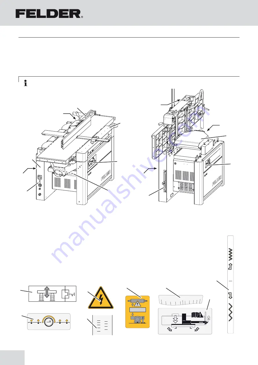
Data plate
"
Motor protection switch button
#
Danger! Electric current!
$
Control panel covers (with options)
depending on the equipment - See chapter entitled:
>Operation and display elements<
%
Scale - Bridge guard
&
Scale - Planer fence
/
Adjusting the planer fence
*
Under table rollers (Option)
)
Gear lever (AD 941)
BL
Changeover position
Fig. 12-1: machine base-frame
12.1 Overview - pictograms, signs and labels
Note: All the pictograms, signs and labels affixed to the machine must be kept visible, readable and may not
be removed.
Annex
12 Annex
Summary of Contents for AD 941
Page 13: ...13 Planer Thicknesser A 941 AD 941 AD 951 Safety...
Page 67: ...67 Planer Thicknesser A 941 AD 941 AD 951 Faults...
Page 69: ...69 Planer Thicknesser A 941 AD 941 AD 951 Annex...
Page 70: ......
Page 71: ......

