28
"
"
#
!
$
%
!
%
#
"
$
#
$
!
"
Planer-Thicknesser
A 941 / AD 941 / AD 951
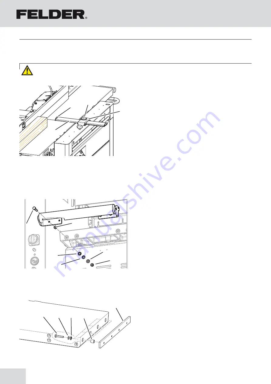
7.6 Assemble the guard rail and bridge guard
1.
Clamping screw: Release
End plug: remove from the guard rail
2.
Protective rail: thread into the arm of the bridge
guard
End plug: insert into the guard rail
3.
Clamping screw: tighten
!
Bridge guard arm
"
Protective rail
#
Clamping screw
$
End plug
Fig. 7-5: Bridge guard
7.7 Assembly workpiece roller / Table extension coupler (Option)
Assembly workpiece roller
1.
Loosely attach the workpiece roller with the
assembled plate to the thicknesser table with screws
and washers.
2.
Subsequently, set the height of the workpiece roller
with an even workpiece.
3.
Tighten the screws once the angularity is set.
!
screw
"
locking nut
#
Shim
$
Ball socket 1
%
Ball socket 2
Assembly of the coupler system:
Place the ball sockets onto the screw. This mounted unit
must be fed through the underside of the table. Place the
spacer sleeve onto the screw; screw on the coupler. (Do
not overtighten). Measure the distance (10 mm) to the
left and to the right with a caliper. With a plastic mallet,
adjust the coupler and tighten the screws.
!
screw
"
Spacer sleeve
#
Coupler
Fig. 7-6: Workpiece roller
Fig. 7-7: Table extension
Attention! Risk of injury! The planer knives are razor sharp.
Setup and installation
Summary of Contents for AD 941
Page 13: ...13 Planer Thicknesser A 941 AD 941 AD 951 Safety...
Page 67: ...67 Planer Thicknesser A 941 AD 941 AD 951 Faults...
Page 69: ...69 Planer Thicknesser A 941 AD 941 AD 951 Annex...
Page 70: ......
Page 71: ......


