57
!
"
%
$
!
!
"
#
%
&
/
(
Planer-Thicknesser
A 941 / AD 941 / AD 951
1.
Position the thicknesser table in the lowest position
(see thicknesser table height adjustment).
Disconnect the machine from the mains power
supply
2.
Loosen the nuts on the sprocket wheels.
Unhook the chain and remove the sprocket wheels.
(on both sides)
3.
Remove the bearing block cover plate.
4.
Attention!
Every adjustment screw is factory set.
These adjustments must be maintained.
Draw a mark with a permanent marker on the
adjustment screw and casting-part.
Then measure the distance with a caliper and make
a note.
5.
Remove the adjusting screws, springs and pressure
bushings.
6.
Pull out the feed roller to the front
7.
To reassemble, follow the instructions in the reverse
order.
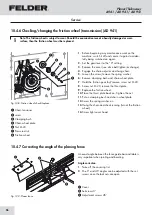
#
Sprocket wheels
$
Bearing block cover plate
%
Adjustment screws
&
Springs
/
Pressure bushings
(
Distance
Note: The rubber infeed and outfeed rollers are prone to wear and tear.
The infeed roller must be replaced if its working surface is worn out or damaged.
10.4.8 Feed rollers/Kickback guard
Fig. 10-10: Feed rollers/Kickback guard
Kickback guard:
• Test the function on a daily basis and remove traces
of resin if necessary.
• When lifted, the guards must drop back into position
due to their own weight.
• Test their function before each use!
Feed rollers:
• Remove traces of resin on a monthly basis, when
depressions appear in the planed workpieces, or in
the event of poor feed.
!
Feed roller
"
Kickback guard
10.4.9 Changing rubber in- and outfeed rollers
Fig. 10-11: Change the feed rollers
Service
Summary of Contents for AD 941
Page 13: ...13 Planer Thicknesser A 941 AD 941 AD 951 Safety...
Page 67: ...67 Planer Thicknesser A 941 AD 941 AD 951 Faults...
Page 69: ...69 Planer Thicknesser A 941 AD 941 AD 951 Annex...
Page 70: ......
Page 71: ......


