mr
.
steam
®
C U S E R I E S
Installation, Operating & Maintenance Manual
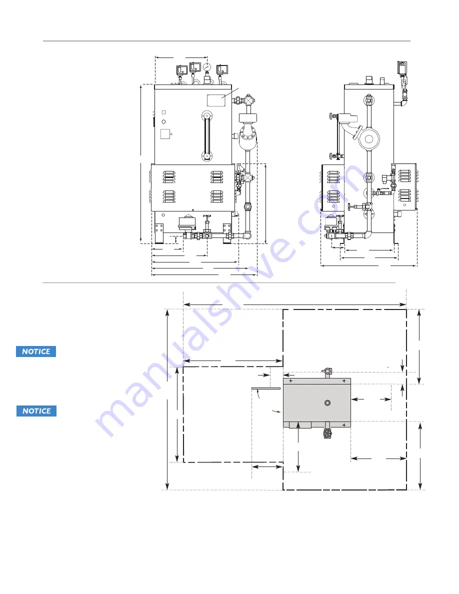
Front
Right Side
31.3
28.3
18.1
34.2
18.7
16.0
30.6
10.3
4.3
2.5
17.2
51.5
25.8
Data
Plate
DIMENSIONS
(cont.)
Figure 4: CU4500
CLEARANCE
SPECIFICATIONS
FOR FIGURE 5 - 7:
Figure 5: CU360-1400
8
Service Area
Clearance
Service Area
Clearance
180
Max
9”
Panel
Clearance
81” (Typ)
36” *
24” **
30” *
61”
(Typ)
24” **
18” ***
24” **
Service Area
Clearance
1” ***
1. MM150 Liquid Level Control on
CU2000 and larger models only.
CU360 to CU1400 have
electronic liquid level controls.
2. Minimum Clear-
ance from Combustible Sur-
faces:
1" above top of CU
generator.
Front of CU generator suitable for
alcove installation only.
Type of flooring: “C", suitable for
combustible flooring.
3. Minimum clearances required
by code are shown.
*
Access to service areas to be supplied by customer. Access door must not be less than 30” wide x 78” high. Refer to
NEC 110.26 for additional code requirements.
**
For ease of servicing, MrSteam recommends a minimum of 24 inches of clearance all around the CU generator.
***
Minimum distance from combustible materials.
16” ***
1” ***
Figure 5: CU360-1400
Figure 4: CU4500


