34
mr
.
steam
®
C U S E R I E S
Installation, Operating & Maintenance Manual
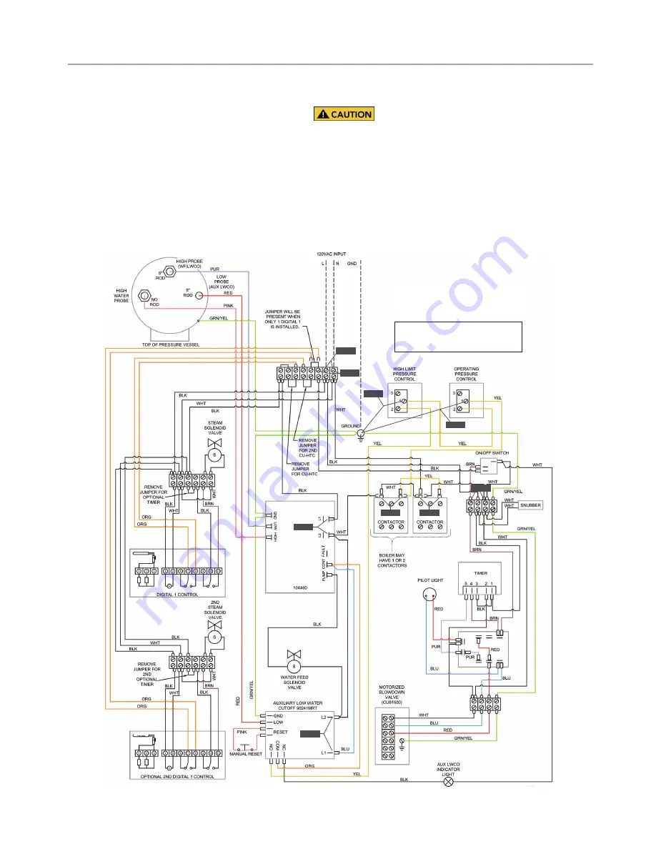
STEP 6 & 7:
Check these terminal points against
a ground or to the boiler jacket and verify that you
have 120V. If you do not have voltage this means
that the controller is tripped on pressure. The
manual high limit can be reset by pushing down
the metallic tab located on the top of the con-
troller.
Be sure to slowly release pressure to zero (0)
psig before resuming operation of steam bath generator.
STEP 8:
Check to see that you have 120V at the contactor.
If you do not then one of your pressure controllers are
tripped. If you have 120V and the contactor is not engaging
then this may indicate a faulty contactor.
Control Circuit Wiring Diagram
TROUBLESHOOTING GUIDE
(cont.)
STEP 3
STEP 6
STEP 1
STEP 7
STEP 4
STEP 2
STEP 5
LEGEND: _____________ FACTORY WIRING
_ _ _ _ _ _ _ _ _ FIELD WIRING
BLK
104460
P R O B E
STEP 8
STEP 8
WIRING DIAGRAM
CONTROL CIRCUIT FOR MODELS
CU360A - 1400A
120 VOLT CONTROL CIRCUIT


