TIMER
SWITCH
PN: 104561
STEAM
SOLENOID
VALVE
DIGITAL 1 CONTROL
N
WHT
L
BLK
S
BLK
BLK
BRN
L
BLK
WHT
RED
BLK
WHT
WHT
GRN
REMOVE
JUMPER
WHEN
INSTALLING
TIMER
mr
.
steam
®
C U S E R I E S
Installation, Operating & Maintenance Manual
Functionality of the Timeswitch
The countdown timer uses a relay to switch the steam sole-
noid on. During the preset running time, the relay energizes
and activates the connected steam solenoid by closing a
circuit. After the time has elapsed, the relay deenergizes
and deactivates the connected steam solenoid by opening
the circuit again. THE TIMER MAY ONLY BE OPERATED
AFTER INSTALLATION IN A PROTECTIVE HOUSING.
BEFORE USE
Before installing and using this timer, it is absolutely neces-
sary that you read this operating manual thoroughly.
SAFETY INSTRUCTIONS
This timer may only be installed by a qualified, licensed
electrician and must be installed in accordance with
National and local codes.
1.
SHOCK HAZARD!
Install the timer per these instruc-
tions before connecting to the main supply. Never touch
live contacts or components.
2. Protection from contact with the line voltage compo-
nents must be achieved by proper installation in a 4 x 4
junction box. When installing the timer, ensure the fasten-
ing sliders prevent the timer from being removed.
3. DO NOT install the timer in a wet or damp location.
4. DO NOT install the timer inside the steam room.
STEAM VENT
IMPORTANT:
A steam vent (PN 104072) must be
installed in the steam line between the steam generator
and the steam solenoid valve when using a 30 minute
timer as shown. The steam vent will release hydrostatic
pressure in the boiler while filling when the 30 minute
timer has timed out.
Make sure the boiler and pipes are not hot
and have no pressure before installing the steam vent.
1. The steam vent shall be plumbed into a Tee in the
steam line between the boiler and the solenoid valve.
Only one steam vent is required, even if the boiler
services two rooms.
2.
IMPORTANT NOTE:
The steam vent should remain
accessible for service.
3. The steam vent should be oriented vertically with the
threads down, as shown in Figure 4.
4. The steam vent is provided with 3/4” NPT male and
1/2” NPT female thread for connecting to the steam
line.
30-MINUTE ROOM TIMER
Interval Timer for CU Commercial Steambaths
Electronic Interval Timer for MrSteam CU Commercial Steambaths
Installation and Operating Manual
30
FUNCTIONALITY OF THE TIMESWITCH
During the preset running time, the timer energizes and
activates the connected steam solenoid by closing a
circuit. After the time has elapsed, the timer
deenergizes and deactivates the connected steam
solenoid by opening the circuit again. THE TIMER MAY
ONLY BE OPERATED AFTER INSTALLATION IN A
PROTECTIVE HOUSING.
BEFORE USE
Before installing and using this timer, it is absolutely nec-
essary that you read this operating manual thoroughly.
SAFETY INSTRUCTIONS
This timer may only be installed by a qualified, licensed
electrician and must be installed in accordance with
National and local codes.
SHOCK HAZARD!
Install the timer per
these instructions before connecting to the main supply.
Never touch live contacts or components.
Protection from contact with the line
voltage components must be achieved by proper
installation in a 2 x 4 junction box. When installing the
timer, ensure the fastening sliders prevent the timer
from being removed.
DO NOT
install the timer in a wet or
damp location.
DO NOT
install the timer inside the
steam room.
Important Note:
As you follow these instructions,
you will notice warning and caution symbols. This
information is important for the safe and efficient
installation and operation of this generator. These are
types of potential hazards that may occur during this
installation and operation:
states a hazard may cause serious injury or
death if precautions are not followed.
signals a situation where minor injury or
product damage may occur if you do not follow
instructions.
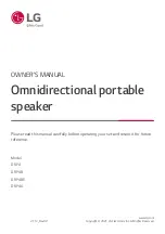
Figure 1:
Wiring Diagram
DIGITAL 30-MINUTE
ROOM TIMER
1. CONNECTING THE TIMER
• Remove one of the knockout holes on the left side of
the boiler jacket.
• Remove the room timer jumper from the terminal
block.
• Connect the timer to the terminal block as shown on
the wiring diagram Figure 1.
• Older models may have some wires and jumpers in
different locations. Please confirm that it matches the
diagram or update it upon installation.
• Mount the timer plate assembly on a 4 x 2 Electrical
box (not supplied).
2. STEAM VENT
IMPORTANT
:
A steam vent (PN 104072) must be
installed in the steam line between the steam generator
and the steam solenoid valve when using a 30 minute
timer as shown. The steam vent will release hydrostatic
pressure in the boiler while filling when the 30 minute
timer has timed out.