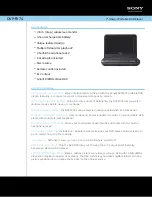
CU AUTOFLUSH
GRN
WHT
BLK
BRN
Blowdown
Control Panel
Terminal Block
in Steam Generator
Panel Interior
Remove Jumper
Snubber
(see note 4)
mr
.
steam
®
C U S E R I E S
Installation, Operating & Maintenance Manual
AUTOMATIC BLOWDOWN SYSTEM
CU81600
The Automatic Blowdown System factory installed items:
• Blowdown Control Panel
• Motorized Drain Valve Assembly
PN CU81600
AUTOMATIC BLOWDOWN SYSTEM KIT INSTALLATION
If the steam generator came with a factory installed
Automatic Blowdown System see page 28 on how to program the timer.
Hazard of Electric Shock. Disconnect all power supplies
before making wiring connections.
Reference applicable wiring diagram.
-81600 Motorized
Drain Valve Assem
bly
Pilot
Light
Timer
Motorized
Blowdown Valve
(CU81600)
AUX LWCO
Automatic
Blowdown Kit
Automatic Blowdown
System Kit Installation
PROGRAMMING
For CU steam bath generators
equipped with Automatic
Blowdown Systems CU81500
and CU81600, refer to the fol-
lowing instructions for time
clock operation and settings.
Timer settings for blowdown
operation are at the discretion
of the owner/operator.
The weekly program dial shows
the seven days of the week and
AM/PM imprints for each day.
The time switch is set by push-
ing the captive trippers to the
outer ring position for the entire
period that the boiler is to be
turned ON, i.e., 2 hours to each
tripper on the 7-day dial. When
the tripper is pushed to the
inside, the boiler is in the OFF
position, and initiating the blow-
down cycle. Due to the timer
having one tripper for every 2
hours, the boiler will need to be
OFF a minimum 2 hours. If less
down time is needed the digital
timer (103662) can be set to the
minute.
1. Remove blank cover and mount the Automatic
Blowdown Control Panel on the front of the genera-
tor cabinet with screws and nuts provided.
2. Remove the jumper between Brown & Black from
the terminal block above the panel.
3. Connect the wires to the terminal block. The termi-
nals are coded with the wire insulation color: Brown-
Black-White-Green.
4. When using the Digital Blowdown timer (PN 103662)
install the Snubber (PN 104251) between the black
and white terminals.
5. Plumb the motorized valve assembly to the genera-
tor drain valve.
6. Install the valve cable in the knockout below the
Automatic Blowdown Control Panel.
7. Connect the wires to the terminal block at the bot-
tom of the panel. The terminals are coded with the
wire insulation color. CU81600: White-Blue-Red-
Green
8. Program the timer and set the clock (see pg. 28)
20