1
2
3
4
4
2
S-834-0005
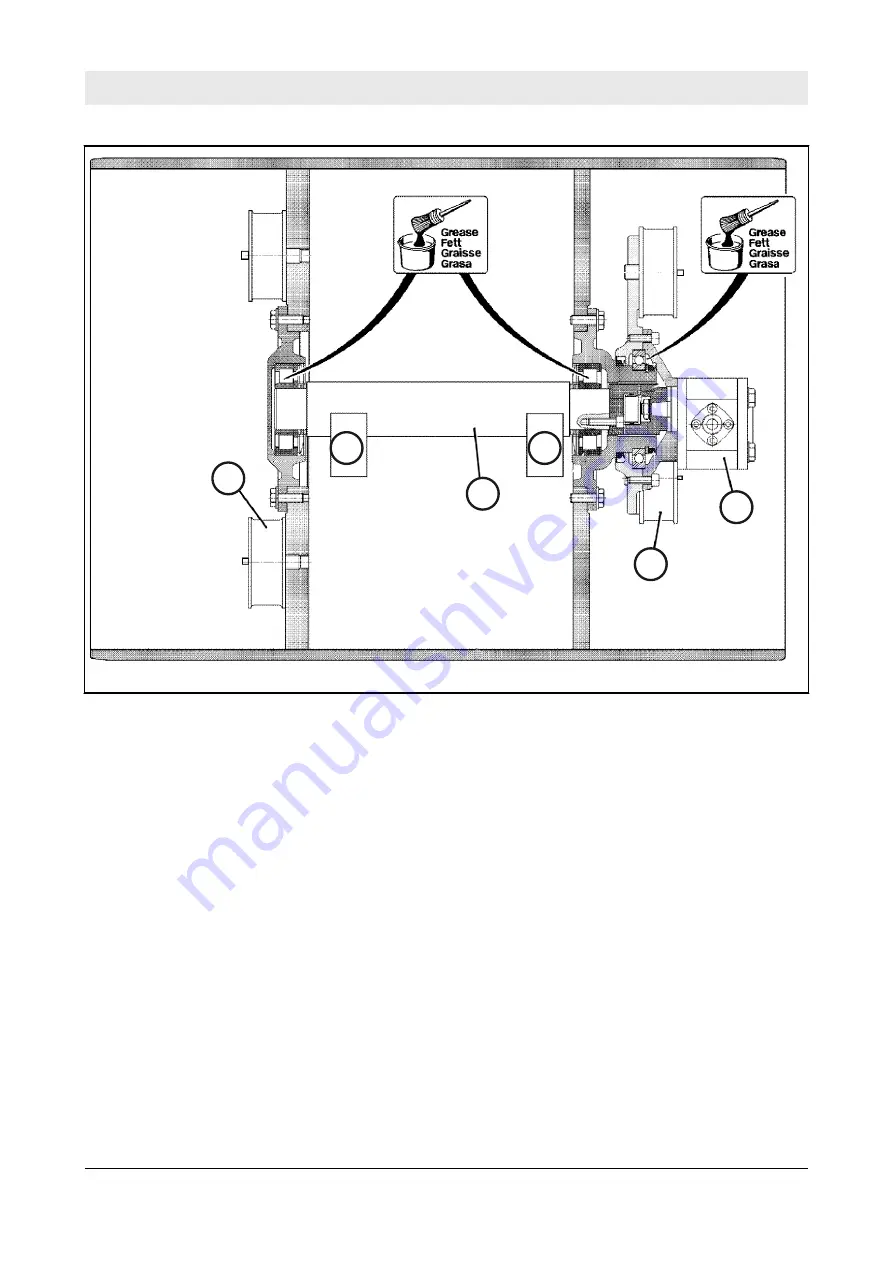
Fig. 100
1
Exciter shaft
2
Rubber buffer
3
Vibration motor
4
Weights
5.4.3 Steering circuit
The steering circuit is an open hydraulic circuit.
Hydraulic system – Description of hydraulic circuits
BW 900-50
118
Go
to
Discount-Equipment.com
to
order
your
parts


