background image

12

ENGLISH

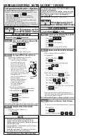
DL1 LED description (Red)

On

At least one of the inputs (safeties, OPEN pulse) is 
engaged or active

Off

No OPEN input is active and no safety device is 
engaged

DL2 LED description (Green)

On 
fixed

Normally active (LED on even if there are no devices 
connected)

Off

BUS-2EASY line short-circuited (flash every 2.5 
sec.)

Rapid 
flashing

An error has been detected in the BUS-2EASY 
connection; repeat the acquisition procedure. If the 
error persists, check that:
• 

the system does not have more than one 
accessory with the same address (see also 
instructions regarding the accessories)

• 

make sure there is no calling error (number of 
devices connected is greater or less than that 
stored during setup)

6.  

Advanced Confi guration

To access Advanced Configuration, press 

F

 and, while holding it, 

also press 

+

:

• when 

+

 is released, the number of the first available function 

will appear

• when 

F

 is also released, the value is displayed, and can be 

changed using 

+

 and 

-

• pressing 

F

 again, and holding it, the name of the next parameter 

will be displayed; when released, the value can be changed 
using 

+

 and 

-

• 

once the last function has been reached, pressing 

F

 makes it 

possible to either save the previously changed parameters or exit 
without saving the changes; the display will go back to showing 
the status of the inputs.

ADVANCED CONFIGURATION


Display

Function

Default

FO

Opening motor power

Adjusts the thrust of the motor during the ope-
ning phase.

00 

Minimum power

50 

Maximum power

40

FC

Closing motor power

Adjusts the thrust of the motor during the closing 
phase.

00 

Minimum power

50 

Maximum power

40

PF

Pre-flashing

This parameter is used to activate the flashing 
lamp for 5 seconds before the selected 
movement.

no 

disabled

OC 

before each movement

CL 

before each closing movement

OP 

before each opening movement

PA 

only at the end of the pause

no

Display

Function

Default

tP

Pre-flashing time

Pre-flashing time expressed in seconds.

00 

minimum pre-flashing

10 

maximum pre-flashing

00

oc

Sensitivity of obstacle during closing 

This determines the sensitivity to an obstacle 
before reversing takes place.

01

 Minimum 

sensitivity 

50

 Maximum 

sensitivity

30

o1

Output 1

Setting this function makes it possible to modify 
the signal type of output 1, allowing high 
connection flexibility with external devices.

00 

Failsafe

0 1


TYPE 1 BEAM ILLUMINATION (output 
active when beam closed, disabled 
with bar open or paused, intermittent 
when moving). 

Use only with output 

4!

02 

BAR LIGHTING TYPE 2 (fl ashing 
output during opening, closing and with 
rod closed or stopped. inactive with rod 
open or paused).

03 

Beam CLOSED

04 

Beam OPEN or in PAUSE, it goes off 
during closing pre-fl ashing.

05


Beam in OPENING MOVEMENT, 
including pre-fl ashing.

06 

Beam in CLOSING MOVEMENT, 

including pre-fl ashing.

07 

Beam STATIONARY

08 

Beam in EMERGENCY mode

09 

LOOP1 engaged

10 

LOOP2 engaged

11 

OPEN for E680 slave

12


CLOSE for E680 slave

13


Beam RELEASED

14 

Not used

15 

Not used

16

 FCA 

engaged

17


FCC engaged

18


Interlock

19


WARNING LAMP (on during opening 
and pause, fl ashing when closing, off 
when the automated system is closed)

20


Battery operation

04

Summary of Contents for B680

Page 1: ...B680H...

Page 2: ......

Page 3: ...NNECTIONS 7 4 1 Terminal board J1 inputs 7 4 2 Terminal board J2 outputs 8 4 3 Terminal board J3 external flashing lamp 8 4 4 Terminal board J4 loop detector 8 4 5 Connector J5 Motor 8 4 6 Connector J...

Page 4: ...AAC declines all liability as concerns safety and efficient operation of the automated system if system components not produced by FAAC are used 19 For maintenance strictly use original parts by FAAC...

Page 5: ...e covering compartment is the same for both models while the bar dimensions differ as shown in detail at bar S and bar L Fig 8 4 INSTALLING THE AUTOMATED SYSTEM 4 1 Preliminary checks For the safety a...

Page 6: ...rrectly operate the barrier pointing out the areas of potential danger 6 MANUAL OPERATION Should manual operation of the barrier be required due to electrical power cut offs or automated system ineffi...

Page 7: ...photocell The barrier is equipped with a lateral covering profile fitted in the compartment opening under which there are holes for containing Safebeam BUS or wireless photocells To install the photoc...

Page 8: ...re upgrade J15 Integrated flashing traffic light connector SW1 Programming key F SW2 Programming key SW3 Programming key SW4 SW5 LOOP 1 LOOP 2 calibration button M1 M1A M2 Optional module connector Co...

Page 9: ...P and GND Fig 26 EMR Emergency contact N C terminal 7 means any device e g switch which if activated in a situation of emergency will open the barrier until the contact is restored When activated this...

Page 10: ...24 25 for OPENING LOOP 2 magnetic loop LOOP 2 SAFETY CLOSE terminals 26 27 for SAFETY CLOSING 4 5 Connector J5 Motor Rapid connector for connecting the motor 4 6 Connector J7 Encoder The B680H barrie...

Page 11: ...details on MASTER SLAVE configuration refer to section 9 MA bu BUS accessories menu For functions associated with this parameter see paragraph 5 3 no Display Function Default LO Operating logics A Aut...

Page 12: ...NG movement to then display 01 once the position of gate OPEN is reached Example of a status sequence displayed starting from a closed barrier The sequence does not include statuses 09 and 10 which co...

Page 13: ...status of the segments of the left hand digit must correspond to the automated system at rest and without pulse generators or or safeties engaged When the CLOSE photocells are engaged the bottom segme...

Page 14: ...mum power 40 FC Closing motor power Adjusts the thrust of the motor during the closing phase 00 Minimum power 50 Maximum power 40 PF Pre flashing This parameter is used to activate the flashing lamp f...

Page 15: ...used together with n C to verify the use of the system and for use of Service Request 00 nC Cycle programming in hundreds of thousands Is used to set a countdown of the system operation cycles the val...

Page 16: ...t have double insulation Make a preferably square or rectangular loop by preparing a PVC cable duct or by tracing the paving as shown in figure 16 the corners must be cut at a 45 angle to avoid cable...

Page 17: ...lways closes 16 When this function is activated during closing the CLOSING SAFETIES stop and allow motion to resume when they are disengaged otherwise they immediately reverse opening Y closes when di...

Page 18: ...value Read only parameter F1 Loop 1 frequency selection This parameter lets you set an oscillation frequency specific to the loop connected to the Loop 1 input or lets the system choose the most adeq...

Page 19: ...is value increases or decreases the output voltage for OUT 5 changing the brightness of the rope light 04 St STATUS OF THE AUTOMATED SYSTEM Exit from programming storage of data and automated system s...

Page 20: ...display the indicationshowntothesideconfirming the fact that there are no engaged photocells or active pulse generators 7 2 Setup Before being put into operation the E680 board requires a setup proced...

Page 21: ...tion systems to the fully closed position with the Mt parameter of the Base configuration level or by operating the release device as indicated in sections 6 and 7 on page 4 3 Access Base programming...

Page 22: ...03 04 05 06 dF Y Y Y Y Y Y Ct MA MA MA MA MA MA bu no no no no no no So 10 10 10 10 10 10 Sc 10 05 05 04 02 02 S1 05 05 05 05 05 05 S2 05 05 05 05 05 05 Advanced Configuration cF 01 02 03 04 05 06 FO...

Page 23: ...eted no effect closes immediately after opening is completed OPEN IN PAUSE resets pause time closes blocks operation closes resets pause time closes when disengaged WHEN CLOSING immediately reverses t...

Page 24: ...ly after opening is completed blocks operation no effect no effect closes immediately after opening is completed OPEN IN PAUSE resets pause time closes blocks operation resets pause time closing inhib...

Page 25: ...time immediately reverses to opening immediately reverses to opening BLOCKED opens and closes after the pause time closes no effect opening and closing inhibited no effect closing inhibited opens and...

Page 26: ...hts Foot 2 3 3 4 4 5 6 6 Foot 2 3 3 4 4 4 5 6 Skirt 2 3 3 4 4 5 6 Skirt Foot 3 3 3 4 4 5 Table 3 12 BALANCING TABLES The following two tables indicate the fixing position of the pistons on the rocker...

Page 27: ...5 5 5 5 6 6 Skirt 4 5 5 5 5 6 6 Skirt Foot 5 5 5 5 5 6 Table 5 13 DEFAULT SELECTION TABLES cF parameter The purpose of the two following tables is to determine depending on the length of the bar and...

Page 28: ...1 5 m m 2 3 X 1 5mm 2 230V 6 6 2 3 4 2 1 1100 mm 900 mm 470 mm 436 m m 280 m m Fig 5 Fig 5 Raccolta immagini Pictures collection Collection d images Photo Kollection Conjunto de imagenes Afbeeldingen...

Page 29: ...27 DX SX Fig 10 Fig 10 Fig 11 Fig 11 M M L1 L2 L3 L1 L2 L3 Fig 12 Fig 12 Fig 13 Fig 13 Fig 14 Fig 14 Fig 15 Fig 15 Fig 16 Fig 16...

Page 30: ...28 Fig 17 Fig 17 L...

Page 31: ...29 Fig 18 Fig 18 Fig 19 Fig 19 1 2 Fig 20 Fig 20...

Page 32: ...30 Fig 21 Fig 21...

Page 33: ...8 9 10 11 SAFE TX CL RX CL 1 2 5 4 3 1 2 12 13 14 15 16 17 18 19 20 21 24 24 24 24 OUT1 OUT2 OUT3 GND Relais NO COM J2 Fig 24 Fig 24 J1 24 GND 24 GND OPEN CLOSE FSW STOP ALARM GND 24 3 4 5 6 7 8 9 10...

Page 34: ...32 DS1 DL1 DL2 BUS BUS RX TX DL2 DS1 ON ON BUS BUS DS1 DL1 DL2 BUS BUS DL2 DS1 ON ON BUS BUS 2EASY 1 2 J6 Fig 28 Fig 28 Fig 27 Fig 27 Fig 29 Fig 29 Fig 30 Fig 30...

Page 35: ...33 Fig 31 Fig 31...

Page 36: ...34 Fig 32 Fig 32...

Page 37: ...B680H Guida per l utente User s guide Instructions pour l utilisateur Anleitungen f r den Benutzer Gu a para el usuario Gebruikersgids...

Page 38: ...anovra prima di inserire il sistema di blocco togliere alimentazione all impianto chiave di sblocco triangolare standard ruotare la chiave in senso orario fino all arresto ed estrarla Fig 18 rif a chi...

Page 39: ...1 Die Firma FAAC lehnt jede Haftung f r Sch den ab die durch unsachgem en oder nicht bestimmungsgem en Gebrauch derAutomatik verursacht werden 2 Die Firma FAAC bernimmt keine Haftung im Falle von nich...

Page 40: ...YSTEEMB680H 1 WAARSCHUWINGEN 1 FAAC aanvaardt geen enkele aansprakelijkheid voor schade die ontstaat uit oneigenlijk gebruik of ander gebruik dan waarvoor het automatische systeem is bedoeld 2 FAACisn...

Page 41: ...5 1 2 Fig 18...

Page 42: ...732719 Rev FAAC S p A Soc Unipersonale Via Calari 10 40069 Zola Predosa BOLOGNA ITALY Tel 39 051 61724 Fax 39 051 758518 www faac it www faacgroup com...

Reviews: