background image

19

ENGLISH

9. MASTER/SLAVE CONFIGURATION

If the installation contemplates the gate area being covered by two opposing barriers, a Master / Slave configuration may be used for the 
boards which will activate the two barriers. This configuration permits connection of the command and safety signals to be simplified (they 
are all connected to just one board), also ensuring perfect synchronisation of the two automated systems.

“MASTER device” means the board to which all the pulse generators and safety devices are connected.
“SLAVE device” means the one controlled by the MASTER via the 2Easy BUS.
Setting the two boards as master and slave must first of all be performed in base level programming by setting the value 

Ct

 = 

MA

 on the 

master board and 

Ct

 = 

SL

 on the slave board.

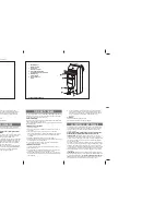
The electrical connection provides for the two automation systems to communicate via the 2Easy BUS using a polarised connection:

Any input signals present on terminal J1 of the SLAVE board will be ignored; connect all control and safety signals to 

the MASTER board

When the BUS connection is made, the SLAVE automation system will synchronise with the MASTER.  Ensure there are 
no people or other obstacles in the range of action of the beam.

To set up the automation systems, proceed as follows:

1. 

Check that the open/close movement is consistent with the button pressed (+ / -) on both barriers via the “Mt” parameter of the base 
configuration level; if not, the motor wiring must be adjusted by inverting the two conductors L1 and L3 as shown in Fig. 14, Ref. 

2. 

Bring the automation systems to the fully closed position with the “Mt” parameter of the Base configuration level or by operating the 
release device as indicated in sections 6 and 7 on page 4.

3. 

Access Base programming on the MASTER device and repeatedly press the 

F

button until you reach the parameter 

tL

, then press the 

+

 and 

-

 buttons at the same time until both automation systems begin opening slowly. 

4. 

On reaching the fully open position, both automation systems will stop automatically.

5. 

The automation systems will then begin the beam closing movement.

6. 

On reaching the closed position, the movement will stop automatically.

7. 

Press the F button to exit the procedure, and confirm you wish to save the data. Check that the current status of the automation system 
shown on the display of both automation systems is  

00

 (closed) and that the rod is in the closed position. If the rod is open and the 

display is showing 

00

, check / adjust the correct direction of movement of the motor again as in step 1 of the procedure.

During setup, a fl ashing 

--

 indication will appear on the display

In MASTER / SLAVE operation mode the two devices will remain independent in terms of their configuration, the forces and speed of move-
ment, the loop detectors and configurable outputs.
The MASTER will, however, overwrite the operational logic on the SLAVE and reading of the SLAVE inputs will be prevented.
When a device is configured as SLAVE, the unused parameters will be hidden in the configuration menus. The following table indicates the 
structure of the menus of a board configured as a SLAVE device.

2Easy

OPEN

CLOSE

FSW

ST

OP

ALARM

GND +24

1 2

3 4 5 6 7 8 9 10 11

BUS

2Easy

OPEN

CLOSE

FSW

ST

OP

ALARM

GND +24

1 2

3 4 5 6 7 8 9 10 11

MASTER board

Ct

 = 

MA

SLAVE board

Ct

 = 

SL

Summary of Contents for B680

Page 1: ...B680H...

Page 2: ......

Page 3: ...NNECTIONS 7 4 1 Terminal board J1 inputs 7 4 2 Terminal board J2 outputs 8 4 3 Terminal board J3 external flashing lamp 8 4 4 Terminal board J4 loop detector 8 4 5 Connector J5 Motor 8 4 6 Connector J...

Page 4: ...AAC declines all liability as concerns safety and efficient operation of the automated system if system components not produced by FAAC are used 19 For maintenance strictly use original parts by FAAC...

Page 5: ...e covering compartment is the same for both models while the bar dimensions differ as shown in detail at bar S and bar L Fig 8 4 INSTALLING THE AUTOMATED SYSTEM 4 1 Preliminary checks For the safety a...

Page 6: ...rrectly operate the barrier pointing out the areas of potential danger 6 MANUAL OPERATION Should manual operation of the barrier be required due to electrical power cut offs or automated system ineffi...

Page 7: ...photocell The barrier is equipped with a lateral covering profile fitted in the compartment opening under which there are holes for containing Safebeam BUS or wireless photocells To install the photoc...

Page 8: ...re upgrade J15 Integrated flashing traffic light connector SW1 Programming key F SW2 Programming key SW3 Programming key SW4 SW5 LOOP 1 LOOP 2 calibration button M1 M1A M2 Optional module connector Co...

Page 9: ...P and GND Fig 26 EMR Emergency contact N C terminal 7 means any device e g switch which if activated in a situation of emergency will open the barrier until the contact is restored When activated this...

Page 10: ...24 25 for OPENING LOOP 2 magnetic loop LOOP 2 SAFETY CLOSE terminals 26 27 for SAFETY CLOSING 4 5 Connector J5 Motor Rapid connector for connecting the motor 4 6 Connector J7 Encoder The B680H barrie...

Page 11: ...details on MASTER SLAVE configuration refer to section 9 MA bu BUS accessories menu For functions associated with this parameter see paragraph 5 3 no Display Function Default LO Operating logics A Aut...

Page 12: ...NG movement to then display 01 once the position of gate OPEN is reached Example of a status sequence displayed starting from a closed barrier The sequence does not include statuses 09 and 10 which co...

Page 13: ...status of the segments of the left hand digit must correspond to the automated system at rest and without pulse generators or or safeties engaged When the CLOSE photocells are engaged the bottom segme...

Page 14: ...mum power 40 FC Closing motor power Adjusts the thrust of the motor during the closing phase 00 Minimum power 50 Maximum power 40 PF Pre flashing This parameter is used to activate the flashing lamp f...

Page 15: ...used together with n C to verify the use of the system and for use of Service Request 00 nC Cycle programming in hundreds of thousands Is used to set a countdown of the system operation cycles the val...

Page 16: ...t have double insulation Make a preferably square or rectangular loop by preparing a PVC cable duct or by tracing the paving as shown in figure 16 the corners must be cut at a 45 angle to avoid cable...

Page 17: ...lways closes 16 When this function is activated during closing the CLOSING SAFETIES stop and allow motion to resume when they are disengaged otherwise they immediately reverse opening Y closes when di...

Page 18: ...value Read only parameter F1 Loop 1 frequency selection This parameter lets you set an oscillation frequency specific to the loop connected to the Loop 1 input or lets the system choose the most adeq...

Page 19: ...is value increases or decreases the output voltage for OUT 5 changing the brightness of the rope light 04 St STATUS OF THE AUTOMATED SYSTEM Exit from programming storage of data and automated system s...

Page 20: ...display the indicationshowntothesideconfirming the fact that there are no engaged photocells or active pulse generators 7 2 Setup Before being put into operation the E680 board requires a setup proced...

Page 21: ...tion systems to the fully closed position with the Mt parameter of the Base configuration level or by operating the release device as indicated in sections 6 and 7 on page 4 3 Access Base programming...

Page 22: ...03 04 05 06 dF Y Y Y Y Y Y Ct MA MA MA MA MA MA bu no no no no no no So 10 10 10 10 10 10 Sc 10 05 05 04 02 02 S1 05 05 05 05 05 05 S2 05 05 05 05 05 05 Advanced Configuration cF 01 02 03 04 05 06 FO...

Page 23: ...eted no effect closes immediately after opening is completed OPEN IN PAUSE resets pause time closes blocks operation closes resets pause time closes when disengaged WHEN CLOSING immediately reverses t...

Page 24: ...ly after opening is completed blocks operation no effect no effect closes immediately after opening is completed OPEN IN PAUSE resets pause time closes blocks operation resets pause time closing inhib...

Page 25: ...time immediately reverses to opening immediately reverses to opening BLOCKED opens and closes after the pause time closes no effect opening and closing inhibited no effect closing inhibited opens and...

Page 26: ...hts Foot 2 3 3 4 4 5 6 6 Foot 2 3 3 4 4 4 5 6 Skirt 2 3 3 4 4 5 6 Skirt Foot 3 3 3 4 4 5 Table 3 12 BALANCING TABLES The following two tables indicate the fixing position of the pistons on the rocker...

Page 27: ...5 5 5 5 6 6 Skirt 4 5 5 5 5 6 6 Skirt Foot 5 5 5 5 5 6 Table 5 13 DEFAULT SELECTION TABLES cF parameter The purpose of the two following tables is to determine depending on the length of the bar and...

Page 28: ...1 5 m m 2 3 X 1 5mm 2 230V 6 6 2 3 4 2 1 1100 mm 900 mm 470 mm 436 m m 280 m m Fig 5 Fig 5 Raccolta immagini Pictures collection Collection d images Photo Kollection Conjunto de imagenes Afbeeldingen...

Page 29: ...27 DX SX Fig 10 Fig 10 Fig 11 Fig 11 M M L1 L2 L3 L1 L2 L3 Fig 12 Fig 12 Fig 13 Fig 13 Fig 14 Fig 14 Fig 15 Fig 15 Fig 16 Fig 16...

Page 30: ...28 Fig 17 Fig 17 L...

Page 31: ...29 Fig 18 Fig 18 Fig 19 Fig 19 1 2 Fig 20 Fig 20...

Page 32: ...30 Fig 21 Fig 21...

Page 33: ...8 9 10 11 SAFE TX CL RX CL 1 2 5 4 3 1 2 12 13 14 15 16 17 18 19 20 21 24 24 24 24 OUT1 OUT2 OUT3 GND Relais NO COM J2 Fig 24 Fig 24 J1 24 GND 24 GND OPEN CLOSE FSW STOP ALARM GND 24 3 4 5 6 7 8 9 10...

Page 34: ...32 DS1 DL1 DL2 BUS BUS RX TX DL2 DS1 ON ON BUS BUS DS1 DL1 DL2 BUS BUS DL2 DS1 ON ON BUS BUS 2EASY 1 2 J6 Fig 28 Fig 28 Fig 27 Fig 27 Fig 29 Fig 29 Fig 30 Fig 30...

Page 35: ...33 Fig 31 Fig 31...

Page 36: ...34 Fig 32 Fig 32...

Page 37: ...B680H Guida per l utente User s guide Instructions pour l utilisateur Anleitungen f r den Benutzer Gu a para el usuario Gebruikersgids...

Page 38: ...anovra prima di inserire il sistema di blocco togliere alimentazione all impianto chiave di sblocco triangolare standard ruotare la chiave in senso orario fino all arresto ed estrarla Fig 18 rif a chi...

Page 39: ...1 Die Firma FAAC lehnt jede Haftung f r Sch den ab die durch unsachgem en oder nicht bestimmungsgem en Gebrauch derAutomatik verursacht werden 2 Die Firma FAAC bernimmt keine Haftung im Falle von nich...

Page 40: ...YSTEEMB680H 1 WAARSCHUWINGEN 1 FAAC aanvaardt geen enkele aansprakelijkheid voor schade die ontstaat uit oneigenlijk gebruik of ander gebruik dan waarvoor het automatische systeem is bedoeld 2 FAACisn...

Page 41: ...5 1 2 Fig 18...

Page 42: ...732719 Rev FAAC S p A Soc Unipersonale Via Calari 10 40069 Zola Predosa BOLOGNA ITALY Tel 39 051 61724 Fax 39 051 758518 www faac it www faacgroup com...

Reviews: