background image

8

ENGLISH

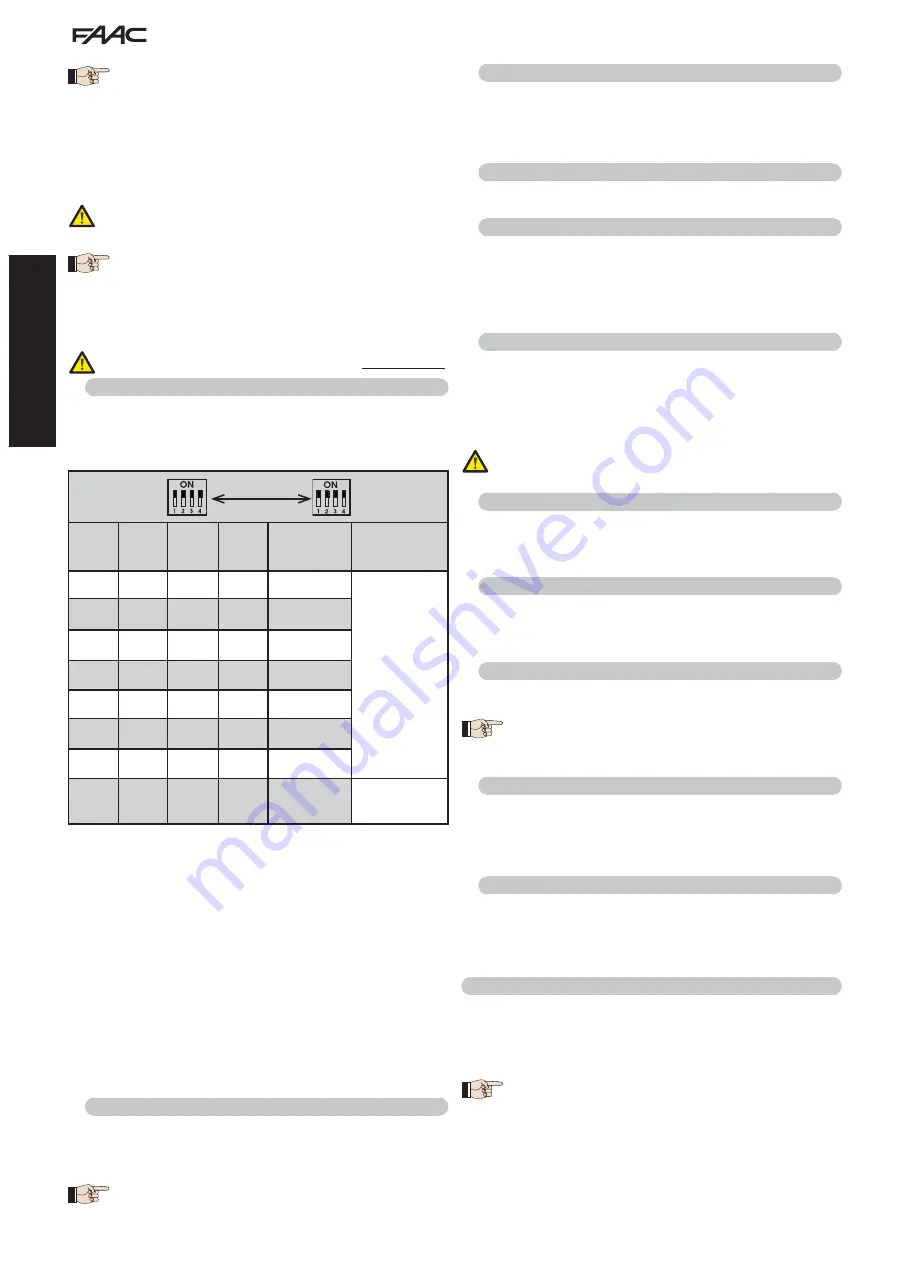
Dip 1 Dip 2 Dip 3 Dip 4

Pair

no.

Type

ON

OFF

OFF

OFF

1° Pair

CLOSE 

photocells

ON

OFF

OFF

ON

2° Pair

ON

OFF

ON

OFF

3° Pair

ON

OFF

ON

ON

4° Pair

ON

ON

OFF

OFF

5° Pair

ON

ON

OFF

ON

6° Pair

ON

ON

ON

OFF

7° Pair

ON

ON

ON

ON

Single

OPEN 

PULSE

DIP-SWITCH

T X

DIP-SWITCH

R X

SAME 

ADDRESS

BUS photocells do not require a matching polarity 
connection. 

The 8 pairs of photocells feature the following functions:
Pairs of closing photocells:   


max 7

Pairs of OPEN pulse photocells: 


max 1

After positioning the BUS technology photocells, it is necessary 
to proceed with selecting the address for each pair using various 
combinations of the DIP-SWITCHES located on each photocell.

Set the SAME DIP-SWITCH ADDRESS chosen both on 
the transmitter and receiver of the same pair.

Ensure that two or more pairs of photocells do not have 
the same address. If no BUS accessories are used, leave 
terminals 1 and 2 free.

The following table describes how to set the dip-switches located 
inside the transmitter and receiver of the BUS photocells.

Addressing BUS photocell PAIRS

To allow operation of the installed BUS accessories, 
store them on the board as described in paragraph 5.3.

4.2  Terminal board J2 (outputs)

OUT 1 - Output 1 open-collector GND (terminal 13):

 The output 

can be set in one of the functions described in the Advanced 
Configuration (par. 6). The default value is 

04 

- Beam OPEN or in 

PAUSE

Maximum load: 24 VDC with 100 mA.

OUT 2 - Output 2 open-collector GND (terminal 15):

 The output can 

be set in one of the functions described in the Advanced Configuration 
(par. 6). The default value is  

03 

- CLOSED BEAM. 

Maximum load: 

2

4 VDC with 100 mA.

OUT 3 - Output 3 open-collector GND (terminal 17): 

The output can 

be set in one of the functions described in the Advanced Configuration 
(par. 6). The default value is 

19 

- WARNING LAMP. 

Maximum load: 

24 VDC with 100 mA.
OUT 4 - Relay output 4 (terminals 19, 20, 21): 

The output can be 

set in one of the functions described in Advanced Configuration (par. 
6). The default value is 

01 

- BEAM ILLUMINATION. 

Maximum load: 

24 VDC with 800 mA.

4.3  Terminal board J3 (external fl ashing lamp)

LAMP:

 to these terminals you can connect a 24VDC FAACLED 

external flashing lamp. 

The integrated flashing traffic light must be 

connected independently to connector J15.

The 24V FAACLIGHT with incandescent lamp cannot be 
connected to the J3 connector 

4.4  Terminal board J4 (loop detector)

LOOP 1: 

magnetic loop LOOP 1 (OPEN, terminals 24-25): for


OPENING.
LOOP 2: 

 magnetic loop LOOP 2 (SAFETY/CLOSE, terminals 26-27): 

for 

SAFETY/CLOSING.

4.5  Connector J5 (Motor)

Rapid connector for connecting the motor.

4.6  Connector J7 (Encoder)

The B680H barrier is equipped with a device for detecting the opening 
angle/bar position to ensure greater anti-crushing safety thanks to 
the possibility of reversing the direction of movement the moment in 
which an obstacle is detected. This device interfaces with the board 
through connector J7.

4.7  Connector J10 (Radio)

Used for the rapid connection of the Minidec, Decoder and RP / RP2 
Receivers (see Fig. 28). If a 2-channel receiver is used, like the RP2, 
it will be possible to directly command automated system OPEN and 
CLOSE from a 2-channel radio control. If a 1-channel receiver is used, 
like the RP, it will only be possible to command OPEN.

Boards should be inserted and removed ONLY after 
having cut off electrical power

4.8  Connector J11 (Beam break-out sensor)

Designed for connecting the break-out sensor for the pivoting beam
(if present). The sensor is optional. If it is not present, 

do not remove

the installed jumper.

4.9  Connector J12 (Emergency battery)

This connector is for connecting a battery (optional) for ensuring 
automated system operation in case of temporary cut off of the main 
power supply.

4.10  Connector J13 (36VDC Power Supply)

This factory-wired connector powers the E680 board.

The terminal shown in Fig. 1 ref. a must be connected 
to the system earth by the installer during the electrical 
connection operations. 

4.11  Connector J15 (fl ashing traffi c light)

This connector is for connecting the flashing traffic light built into 
the barrier head. The flashing traffic light visually signals barrier 
movement and, if needed, regulate access to the property using 
traffic light signals. 

4.12  Connector J16 (beam lights)

Connector which allows the rope light for the rod to be connected, 
providing visual warning of barrier movement. The connector has a 
common GND connection and two +36V (BLR / BRG) outputs. The 
default value is 02 - “BEAM LIGHTING TYPE 2” for OUT 5, 04 - “BEAM 
OPEN OR PAUSED” for OUT 6. 

5. PROGRAMMING

The E680 board features 3 programming levels that make it entirely 
configurable and allow it to adapt the logics to any use.
Each of the three levels can be accessed through a specific key 
combination.

Changes to the confi guration parameters become 
effective immediately, while final storage occurs 
only upon exiting confi guration and returning to the 
automated system status display. If the equipment is 
powered down before returning to the automated system 
status display, all changes made will be lost.

Summary of Contents for B680

Page 1: ...B680H...

Page 2: ......

Page 3: ...NNECTIONS 7 4 1 Terminal board J1 inputs 7 4 2 Terminal board J2 outputs 8 4 3 Terminal board J3 external flashing lamp 8 4 4 Terminal board J4 loop detector 8 4 5 Connector J5 Motor 8 4 6 Connector J...

Page 4: ...AAC declines all liability as concerns safety and efficient operation of the automated system if system components not produced by FAAC are used 19 For maintenance strictly use original parts by FAAC...

Page 5: ...e covering compartment is the same for both models while the bar dimensions differ as shown in detail at bar S and bar L Fig 8 4 INSTALLING THE AUTOMATED SYSTEM 4 1 Preliminary checks For the safety a...

Page 6: ...rrectly operate the barrier pointing out the areas of potential danger 6 MANUAL OPERATION Should manual operation of the barrier be required due to electrical power cut offs or automated system ineffi...

Page 7: ...photocell The barrier is equipped with a lateral covering profile fitted in the compartment opening under which there are holes for containing Safebeam BUS or wireless photocells To install the photoc...

Page 8: ...re upgrade J15 Integrated flashing traffic light connector SW1 Programming key F SW2 Programming key SW3 Programming key SW4 SW5 LOOP 1 LOOP 2 calibration button M1 M1A M2 Optional module connector Co...

Page 9: ...P and GND Fig 26 EMR Emergency contact N C terminal 7 means any device e g switch which if activated in a situation of emergency will open the barrier until the contact is restored When activated this...

Page 10: ...24 25 for OPENING LOOP 2 magnetic loop LOOP 2 SAFETY CLOSE terminals 26 27 for SAFETY CLOSING 4 5 Connector J5 Motor Rapid connector for connecting the motor 4 6 Connector J7 Encoder The B680H barrie...

Page 11: ...details on MASTER SLAVE configuration refer to section 9 MA bu BUS accessories menu For functions associated with this parameter see paragraph 5 3 no Display Function Default LO Operating logics A Aut...

Page 12: ...NG movement to then display 01 once the position of gate OPEN is reached Example of a status sequence displayed starting from a closed barrier The sequence does not include statuses 09 and 10 which co...

Page 13: ...status of the segments of the left hand digit must correspond to the automated system at rest and without pulse generators or or safeties engaged When the CLOSE photocells are engaged the bottom segme...

Page 14: ...mum power 40 FC Closing motor power Adjusts the thrust of the motor during the closing phase 00 Minimum power 50 Maximum power 40 PF Pre flashing This parameter is used to activate the flashing lamp f...

Page 15: ...used together with n C to verify the use of the system and for use of Service Request 00 nC Cycle programming in hundreds of thousands Is used to set a countdown of the system operation cycles the val...

Page 16: ...t have double insulation Make a preferably square or rectangular loop by preparing a PVC cable duct or by tracing the paving as shown in figure 16 the corners must be cut at a 45 angle to avoid cable...

Page 17: ...lways closes 16 When this function is activated during closing the CLOSING SAFETIES stop and allow motion to resume when they are disengaged otherwise they immediately reverse opening Y closes when di...

Page 18: ...value Read only parameter F1 Loop 1 frequency selection This parameter lets you set an oscillation frequency specific to the loop connected to the Loop 1 input or lets the system choose the most adeq...

Page 19: ...is value increases or decreases the output voltage for OUT 5 changing the brightness of the rope light 04 St STATUS OF THE AUTOMATED SYSTEM Exit from programming storage of data and automated system s...

Page 20: ...display the indicationshowntothesideconfirming the fact that there are no engaged photocells or active pulse generators 7 2 Setup Before being put into operation the E680 board requires a setup proced...

Page 21: ...tion systems to the fully closed position with the Mt parameter of the Base configuration level or by operating the release device as indicated in sections 6 and 7 on page 4 3 Access Base programming...

Page 22: ...03 04 05 06 dF Y Y Y Y Y Y Ct MA MA MA MA MA MA bu no no no no no no So 10 10 10 10 10 10 Sc 10 05 05 04 02 02 S1 05 05 05 05 05 05 S2 05 05 05 05 05 05 Advanced Configuration cF 01 02 03 04 05 06 FO...

Page 23: ...eted no effect closes immediately after opening is completed OPEN IN PAUSE resets pause time closes blocks operation closes resets pause time closes when disengaged WHEN CLOSING immediately reverses t...

Page 24: ...ly after opening is completed blocks operation no effect no effect closes immediately after opening is completed OPEN IN PAUSE resets pause time closes blocks operation resets pause time closing inhib...

Page 25: ...time immediately reverses to opening immediately reverses to opening BLOCKED opens and closes after the pause time closes no effect opening and closing inhibited no effect closing inhibited opens and...

Page 26: ...hts Foot 2 3 3 4 4 5 6 6 Foot 2 3 3 4 4 4 5 6 Skirt 2 3 3 4 4 5 6 Skirt Foot 3 3 3 4 4 5 Table 3 12 BALANCING TABLES The following two tables indicate the fixing position of the pistons on the rocker...

Page 27: ...5 5 5 5 6 6 Skirt 4 5 5 5 5 6 6 Skirt Foot 5 5 5 5 5 6 Table 5 13 DEFAULT SELECTION TABLES cF parameter The purpose of the two following tables is to determine depending on the length of the bar and...

Page 28: ...1 5 m m 2 3 X 1 5mm 2 230V 6 6 2 3 4 2 1 1100 mm 900 mm 470 mm 436 m m 280 m m Fig 5 Fig 5 Raccolta immagini Pictures collection Collection d images Photo Kollection Conjunto de imagenes Afbeeldingen...

Page 29: ...27 DX SX Fig 10 Fig 10 Fig 11 Fig 11 M M L1 L2 L3 L1 L2 L3 Fig 12 Fig 12 Fig 13 Fig 13 Fig 14 Fig 14 Fig 15 Fig 15 Fig 16 Fig 16...

Page 30: ...28 Fig 17 Fig 17 L...

Page 31: ...29 Fig 18 Fig 18 Fig 19 Fig 19 1 2 Fig 20 Fig 20...

Page 32: ...30 Fig 21 Fig 21...

Page 33: ...8 9 10 11 SAFE TX CL RX CL 1 2 5 4 3 1 2 12 13 14 15 16 17 18 19 20 21 24 24 24 24 OUT1 OUT2 OUT3 GND Relais NO COM J2 Fig 24 Fig 24 J1 24 GND 24 GND OPEN CLOSE FSW STOP ALARM GND 24 3 4 5 6 7 8 9 10...

Page 34: ...32 DS1 DL1 DL2 BUS BUS RX TX DL2 DS1 ON ON BUS BUS DS1 DL1 DL2 BUS BUS DL2 DS1 ON ON BUS BUS 2EASY 1 2 J6 Fig 28 Fig 28 Fig 27 Fig 27 Fig 29 Fig 29 Fig 30 Fig 30...

Page 35: ...33 Fig 31 Fig 31...

Page 36: ...34 Fig 32 Fig 32...

Page 37: ...B680H Guida per l utente User s guide Instructions pour l utilisateur Anleitungen f r den Benutzer Gu a para el usuario Gebruikersgids...

Page 38: ...anovra prima di inserire il sistema di blocco togliere alimentazione all impianto chiave di sblocco triangolare standard ruotare la chiave in senso orario fino all arresto ed estrarla Fig 18 rif a chi...

Page 39: ...1 Die Firma FAAC lehnt jede Haftung f r Sch den ab die durch unsachgem en oder nicht bestimmungsgem en Gebrauch derAutomatik verursacht werden 2 Die Firma FAAC bernimmt keine Haftung im Falle von nich...

Page 40: ...YSTEEMB680H 1 WAARSCHUWINGEN 1 FAAC aanvaardt geen enkele aansprakelijkheid voor schade die ontstaat uit oneigenlijk gebruik of ander gebruik dan waarvoor het automatische systeem is bedoeld 2 FAACisn...

Page 41: ...5 1 2 Fig 18...

Page 42: ...732719 Rev FAAC S p A Soc Unipersonale Via Calari 10 40069 Zola Predosa BOLOGNA ITALY Tel 39 051 61724 Fax 39 051 758518 www faac it www faacgroup com...

Reviews: