background image

C030543


VER 20a


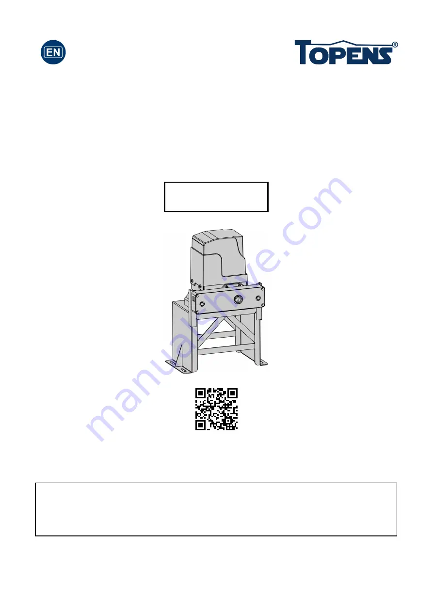
Sliding Gate Opener 

User’s Manual 


Model: 


TOPENS Website 

http://www.topenstool.com/ 


CK2600 


Please read and follow all warnings, precautions and instructions before 

installation and use. 


Periodic checks of the opener are required to ensure safe operation. 


Save this manual. 

Summary of Contents for CK2600

Page 1: ...r s Manual Model TOPENS Website http www topenstool com CK2600 Please read and follow all warnings precautions and instructions before installation and use Periodic checks of the opener are required to ensure safe operation Save this manual ...

Page 2: ...nical Specifications Features 5 Installation Overview 6 Installation of the Opener 6 Manual Operation 7 Installation of chain and chain brackets 8 Install the magnets for Limit Switches 9 Connecting of Power Supply 9 Connecting of the Control Board 10 Setting of the Control Board 12 How to Program or Erase the Remote 13 How to Use the Remote to Operate Your Gate Opener 13 Wireless Keypad Programmi...

Page 3: ...he factory declines all responsibility for any consequences resulting from failure to observe Good Technical Practice when constructing closing structures door gates etc as well as from any deformation which might occur during use Disconnect the electrical power supply before carrying out any work on the installation Also disconnect any buffer batteries if fitted Fit an omnipolar or magnetothermal...

Page 4: ...re suitable the gate should be mounted and moving freely Check that the structure is sufficiently strong and rigid and that its dimensions and weights conform to those listed in the specifications table of this document Make sure that the gate is plumb and level The fence posts must be mounted in concrete The gate does not bind or drag on the ground The gate manual operation can be carried out smo...

Page 5: ...4 Parts List ...

Page 6: ...le at TOPENS Store Technical Specifications Features Specifications CK2600 Power input 110V 120V 60Hz or 220 240V 50Hz Motor voltage 120VAC or 230VAC Rated power 1000W Gate moving speed 20 cm s 8 in s Max gate weight 2600kg 5700lbs Max torque 75Nm Environmental conditions 20 50 4 F to 122 F Protection class IP44 ...

Page 7: ...e electromagnetism limit for easy adjustment Can be equipped with wide range accessories Installation Overview Installation of the Opener Caution Be sure that the opener is installed in a level and paralleled position and is properly secured Improper installation could result in property damage severe injury and or death Before starting installation ensure that there is no point of friction during...

Page 8: ...tly level 4 The four anchor bolts must be set into the concrete when it is poured make sure the position of anchor bolts was placed according to the position of mounting holes on the base plate before concrete become harden 5 Mount the base plate to the concrete Pad It s only temporary installation Further adjustment will be required when install the chain 6 Mount the chain box to the base plate b...

Page 9: ...ion later 3 Connect second chain bolt with another end of chain from chain box then attach bolt to the L bracket on opposite end of gate using the washers and nuts 4 Make sure that the chain is line up exactly with the position where the chain on the chain idler wheel 5 Set appropriated chain tension by adjusting two chain bolts of the both end Cut the unwanted length of chain if necessary 6 Fix t...

Page 10: ...es it The lower magnet bracket must be installed at left side and higher magnet bracket must be installed at right side from the view inside of property Finally adjust the magnet to the proper position by moving the gate with the motor The magnet should be 20 30mm away from the magnetic limit switch If it is too far away the switch will fail to work The distance between the magnet and the opener s...

Page 11: ...10 respectively and connect the earth wire to 2 terminal of the control board NOTE The power supply cord is not included in the package Connecting of the Control Board ...

Page 12: ...als in parallel Use another 2 core cable to connect the NC terminal of the receiver to the 14 terminal the COM terminal to the 15 terminal 5 Push Button Optional The push button should be wired to the 15 and 16 terminals The gate opener works alternately by pushing the button open stop close stop open 6 Exit Wand Optional First insert the Adapter BOARD into the CONTROL BOARD and then connect the w...

Page 13: ...nables user to drive the vehicle through the gate quickly when the gate opens to certain width DIP Switch 1 ON 4 Seconds OFF 0 DIP Switch 2 ON 2 Seconds OFF 0 NOTE The midway mode function would be disabled if both DIP switches are turned off Factory default setting is disabled The midway mode could be activated by pressing button B of the remote control when the gate is in the full closed positio...

Page 14: ...emote codes Press and hold the learn button until the REM LED light is off Now all remote codes have been erased NOTE Max 8 remotes can be programmed for the opener An External Receiver optional allows up to 250pcs remotes to be programmed for the opener TOPENS ERM12 Universal External Receiver is available at TOPENS Store TOPENS ERM12 Universal External Receiver is also compatible with other bran...

Page 15: ...operate the opener Also you can change the password of the keypad follow the below steps Press PIN and then input the six digits old password and then press PIN again the REM LED will be ON Input the six digits new password and then press the PIN to confirm the new setting REM LED will flash for 3 seconds and then be OFF which indicates the password has been changed successfully You can press PIN ...

Page 16: ... suitable for receiver After making sure the codes are correct erase remote controls and then re program the codes in the device 4 Check the control board Replace the control board as necessary The gate opens but stops and will not return 1 Check the installing position of the magnets The opener would not run if both of the limit switches are activated by one magnet 2 Check the limit switch Remove...

Page 17: ... Check and tighten anchors bolts Check for loose or corroded wire Ensure the opener is well earthed and correctly terminated Always check the Stop Reverse in case of obstruction function when performing any maintenance If this function can t be made operable remove this opener from service until the cause of the malfunction is identified and corrected ...

Page 18: ...se do not hesitate to contact us E mail support topenstool com Kindly include your Product Model Purchasing Date Site Order and your contact information All your concerns will be replied within 24 hours Tel 86 571 8908 0213 China Mon Fri 9 00AM 5 30PM UTC 08 00 ...

Reviews: