Extron electronics mediaport 200 User Manual Download Page 33

MediaPort 200 • Installation

26

4. 

Windows XP or earlier:

 When the 

Completed

 screen appears, click 

Finish

 to close 

the wizard. 

Windows 7 or later: 

When the USB software has been located and downloaded, the 

message 

Ready


to


use

 appears on the 

Driver


Software


Installation

 screen (a 

pop-up message appears above the Windows taskbar if the screen is closed). Click 

Close

 to close the status window. 

5. 

Configure the MediaPort as desired, using PCS configuration software (see 

Product 

Configuration Software (PCS)

 on page 34), the front panel menus (see 

Menus on 

the LCD Screen 

on page 63), or SIS commands (see 

SIS Commands 

on  

page 112).

Connecting to the RS-232 Port

To connect the computer or control system to the MediaPort RS-232 port, use an Extron 
Universal Control cable or other female 9-pin-to-bare-wire RS-232 cable. 

NOTE:

 The MediaPort RS-232 port has a fixed baud rate of 9600.

1. 

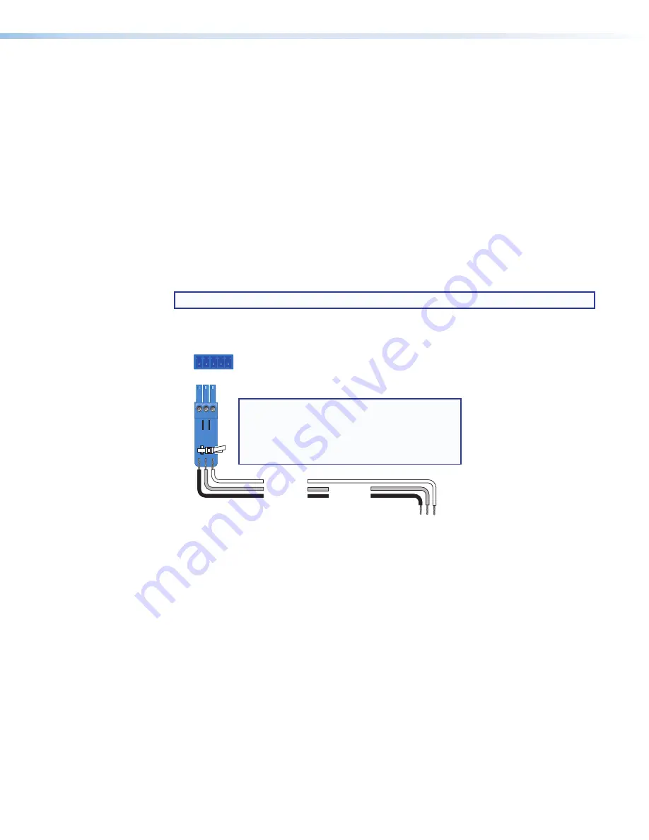
Wire the unterminated end of the RS-232 cable to the provided 3-pole captive screw 
connector as shown in figure 21


below:

RS-232

Computer 
RS-232 Port

MediaPort 200 Rear Panel
RS-232 Port

NOTES:  


  If you use cable that has a drain wire, tie     

the drain wire to ground at both ends.


  Connect a ground wire between the

MediaPort and the computer.

Tx Rx

1   2   3

G

Ground (G) 

Transmit (Tx) 

Receive (Rx) 

Transmit (Tx)

Receive (Rx)

Figure 21. 

Connecting to the RS-232 Port

a. 

Connect


the transmit wire to the left pin of the connector, which plugs into the Tx 

(transmit) port on the rear panel.

b. 

Connect the receive wire to the second pin, which plugs into the Rx (receive) port.

c. 

Connect the ground wire to the last pin, which plugs into the ground port, marked 
with G. 

2. 

Connect the 9-pin connector end of the RS-232 cable to the serial port of the 
computer.

3. 

Plug the wired 3-pole captive screw connector into the first three slots (labeled Tx Rx G) 
of the 5-pole RS-232/+12V captive screw connector on the MediaPort rear panel (see 

figure 11


K

 on page 19).

See 

SIS Commands 

on page 112


for information on sending configuration and control 

commands to this port.

figure 21.  

Connecting to the RS-232 Port

Summary of Contents for mediaport 200

Page 1: ...User Guide MediaPort 200 Scalers HDMI and Audio to USB Scaling Bridge 68 2755 01 Rev C 12 16...

Page 2: ...encia 68 290 01 en el sitio Web de Extron www extron com Instructions de s curit Fran ais AVERTISSEMENT Ce pictogramme lorsqu il est utilis sur le produit signale l utilisateur la pr sence l int rieur...

Page 3: ...Hideaway Inline IP Intercom IP Link Key Minder LinkLicense LockIt MediaLink MediaPort NetPA PlenumVault PoleVault PowerCage PURE3 Quantum SoundField SpeedMount SpeedSwitch System INTEGRATOR TeamWork...

Page 4: ...ses and can radiate radio frequency energy and if not installed and used in accordance with the instruction manual may cause harmful interference to radio communications Operation of this equipment in...

Page 5: ...5 17 03 EX X1 X2 X2 X2 CE NOTE For commands and examples of computer or device responses mentioned in this guide the character 0 is used for the number zero and O is the capital letter o Computer resp...

Page 6: ...nfiguration Menu 74 Introduction 1 About this Guide 1 About the MediaPort 200 1 Features 2 USB Video 5 Audio Functions 5 Application Diagrams 6 Theory of Operation 7 MediaPort 200 Operational Modes 7...

Page 7: ...uts 94 USB Playback Input 94 Line Input analog 94 HDMI Input 95 Audio Line Outputs 95 Analog Line Output 95 USB Line Output 95 Ref and Aux Outputs 95 Application Setup Examples 96 Application 1 MediaP...

Page 8: ...terms external DSP matrix processor external DSP Processor and DSP are also used interchangeably About the MediaPort 200 The MediaPort 200 is an HDMI and audio to USB scaling bridge that interfaces b...

Page 9: ...and signal processing capabilities including mixing and routing for 4x2 audio The DSP is optimized for integration with mic and program audio sources as well as software codecs hardware codecs externa...

Page 10: ...or is selectable for all audio outputs including USB audio to the computer and aids in optimizing audio output signals Picture controls for brightness contrast horizontal and vertical positioning and...

Page 11: ...imal minimum and maximum levels This prevents operators from working with digital I O RS 232 or Ethernet control from exceeding pre defined limits Live DSP configuration Allows live parameter adjustme...

Page 12: ...t 200 When a Universal Communications UC application on the host PC is launched it requests the desired video resolution in real time from the MediaPort 200 based on host PC hardware usage available n...

Page 13: ...iPod Video Audio WiFi 1 2 3 4 WiFi 1 2 3 4 WiFi 1 2 3 4 WiFi 1 2 3 4 Figure 1 Application 1 Standalone MediaPort 200 MediaPort 200 100 240V 0 4A MAX 50 60 Hz HDMI LOOP OUT MIC LINE 48V LINE L R LINE L...

Page 14: ...Port accepts a single microphone at the Mic Line input or can accept a microphone mix from an external DSP matrix processor The following MediaPort audio modes are selectable in the Extron Product Con...

Page 15: ...d prevent it from being sent back to the far end Standalone Mode In the Standalone audio mode the computer recognizes the MediaPort as a Speakerphone In this mode Speakerphone MediaPort 200 is chosen...

Page 16: ...outed to USB Out L R NOTE USB Communications audio is never routed to USB Out Line Out Set to Stereo Mode default dual mono available Line input L is routed to Line output L Line input R is routed to...

Page 17: ...MIC LINE IN GAIN DUCKER GAIN COMP FLT USB OUT L USB OUT R LINE OUT L LINE OUT R LIM LIM LIM LIM FLT FLT FLT FLT ATT ATT ATT ATT SIG GEN SIG GEN SIG GEN SIG GEN REF OUT ATT SIG GEN AUX OUT ATT SIG GEN...

Page 18: ...R GAIN GAIN GAIN DUCKER DUCKER HDMI IN L GAIN USB PLAYBACK L USB PLAYBACK R GAIN GAIN GAIN GAIN COMP COMP COMP COMP FLT FLT FLT FLT COMP COMP FLT FLT COMP COMP FLT FLT MIC LINE IN GAIN DUCKER GAIN CO...

Page 19: ...HDMI IN R USB OUT L USB OUT R LINE OUT L LINE OUT R LIM LIM LIM LIM FLT FLT FLT FLT LINE IN L GAIN GAIN GAIN GAIN ATT ATT ATT ATT TRIM TRIM TRIM TRIM USB COMMUNICATIONS L USB COMMUNICATIONS R GAIN GA...

Page 20: ...red Mix to Far End Mic purple Program green MIC PROGRAM PROGRAM MIX MIX TO FAR END USB PLAYBACK NEAR END HDMI LINE IN MUTE MUTE MUTE MUTE MUTE MUTE MUTE USB COMMUNICATIONS STEREO DUAL MONO STEREO DUAL...

Page 21: ...signal is sent to the Line output and Ref output as well as when it is just sent to the Ref output When the Mix USB Communications in the box in the Near End panel of the Mix tab is checked USB commun...

Page 22: ...MMUNICATIONS STEREO DUAL MONO STEREO DUAL MONO FROM FAR END ROOM VOLUME Mix USB Communication Mix USB Playback Figure 9 Mix Controls Typically mic audio level is set higher than program audio It is re...

Page 23: ...in PCS see Input Tab on page 51 Settings for Ref and Aux outputs attenuation controls may remain at 0 dB for unity gain in most cases Adjust the output controls if the device connected to these outpu...

Page 24: ...application that AEC needs to be applied at the UC application level in the signal chain See General Settings Tab on page 59 for information on how to select audio modes External DSP with AEC Mode In...

Page 25: ...dows The following topics are discussed Rear Panel Connections Securing the HDMI Connectors Using the LockIt HDMI Lacing Brackets Connecting for Remote Control Configuring Host Computer for MediaPort...

Page 26: ...A MAX 50 60 Hz HDMI LOOP OUT MIC LINE 48V LINE L R LINE L R REMOTE OUTPUT LAN USB REF AUX RESET RS 232 12V I O Tx 0 1A MAX Rx G I1 I2 G O1 O2 INPUT H H G G F F D D C C A A E E J J I I K K L L M M B B...

Page 27: ...les d nuder La longueur id ale est de 5 mm 3 16 inches S ils sont un peu plus longs les c bles expos s pourraient se toucher et provoquer un court circuit S ils sont un peu plus courts ils pourraient...

Page 28: ...page 73 SIS commands see the USB Output Format on page 127 This connector provides audio send and return which allows audio from the connected computer to be input to the MediaPort and mixed to the au...

Page 29: ...ch as a digital I O device that illuminates LEDs for a microphone or switch plate to the and pins of this connector L Digital I O Connector This 5 pole 3 5 mm captive screw connector contains two digi...

Page 30: ...facilement tre d nud 4 Loosely place the included tie wrap around the HDMI connectors and the bracket 5 While holding the connector securely against the lacing bracket tighten the tie wrap then remov...

Page 31: ...reens may open Windows XP and earlier If the following screen is displayed specify whether the computer should connect to Windows Update to search for the driver to communicate with the MediaPort via...

Page 32: ...ndows taskbar showing that Windows is searching Windows Update for USB software If desired click the USB icon to view the progress of the search The Driver Software Installation window appears Figure...

Page 33: ...the RS 232 cable to the provided 3 pole captive screw connector as shown in figure 21 below RS 232 Computer RS 232 Port MediaPort 200 Rear Panel RS 232 Port NOTES If you use cable that has a drain wir...

Page 34: ...e computer running Windows 7 The appropriate drivers install automatically Figure 22 below shows the message that is displayed above the Windows taskbar during driver installation Figure 22 Driver Ins...

Page 35: ...tallation 28 4 On the Playback control panel right click Speakers Extron MediaPort 200 see figure 24 1 below 5 From the drop down menu select Set as Default Device 2 Figure 24 Setting Speakers as Defa...

Page 36: ...n 29 6 Right click Speakerphone Extron MediaPort 200 see figure 25 1 below and select Set as Default Communication Device 2 from the drop down menu Figure 25 Setting Speakerphone as Default Playback C...

Page 37: ...26 Default Device and Communications Icons on the Playback Screen 7 Click the Recording tab in the Sound dialog box 8 On the Recording control panel right click Speakerphone Extron MediaPort 200 see...

Page 38: ...200 Installation 31 The Recording control panel opens with a check mark 4 beside the Speakerphone MediaPort 200 device icon see figure 28 below Figure 28 MediaPort 200 Speakerphone Selected on Recordi...

Page 39: ...cation and select Tools Options from the menu bar or click the Options icon near the right edge of the main dialog box see the illustration at right The Options dialog box opens 2 Click Audio Device s...

Page 40: ...n 33 5 In the left panel click Video Device see figure 30 1 below 6 From the Video Device drop down menu select MediaPort 200 Video 2 7 Click OK 3 The Options dialog box closes Figure 30 Options Dialo...

Page 41: ...r Tab Picture Config Tab Audio Config Tab General Settings Tab Downloading the PCS Software To use the Product Configuration Software download the software from the PCS Download Page and install it on...

Page 42: ...t opens and restart this procedure at step 6 If instead a Download icon at the bottom of the page appears wait until the icon displays the name pcss_vnxnxn exe then click it 5 On the next prompt windo...

Page 43: ...n the PCS main window locate the desired MediaPort in the Device Discovery panel and click its name to select it see figure 32 1 below TIP If the MediaPort 200 does not have a user defined name see Ge...

Page 44: ...see figure 33 1 above and the password if one is required The default IP address is 192 168 254 254 2 Click Connect 2 The MediaPort main window opens see figure 34 below Figure 34 PCS Main Window for...

Page 45: ...From the Download Center page select M figure 36 3 below from the alphabetized list at the top of the page 4 Next click Download 4 in the MediaPort 200 box Figure 36 MediaPort 200 Firmware Download Li...

Page 46: ...re 37 Accessing Update Firmware 5 From the Update Firmware to This Device dialog box click Open Firmware File see figure 38 4 below and browse the disk for the firmware file default location is Progra...

Page 47: ...es status indicators and configuration for the following video inputs and outputs 1 HDMI Input on page 41 3 USB Output on page 42 2 HDMI Loop on page 42 4 Test Patterns on page 43 Figure 39 Input Outp...

Page 48: ...lows the aspect ratio of the input signal maintaining the input s native aspect ratio with regard to the current USB output resolution 5 Auto Memory When checked default Auto Memory automatically save...

Page 49: ...the video signal USB Output Figure 42 USB Output Panel 1 Resolution This view only field displays the resolution being sent by the USB Output 2 Format This drop down menu allows selection of USB vide...

Page 50: ...actory default EDID into the PCS software EDID library and save the EDID from a connected MediaPort 200 user assigned memory slot or the EDID from a display connected to the MediaPort HDMI Loop output...

Page 51: ...ction without having to search through all available EDID EDID can be clicked and dragged from the Available EDID panel into the Favorites panel to be added as a favorite To remove a favorite from the...

Page 52: ...the library of available EDID configurations located on the connected MediaPort 200 and the host PC Input Figure 49 Input Panel The Input panel displays the current EDID configuration of the source c...

Page 53: ...ser and input presets and applies overscan The following panels are available on the Picture Config tab 1 Adjust Graphically on page 47 4 Signal Sampling and Overscan on page 49 2 Adjust Numerically o...

Page 54: ...gives the user handles on the top bottom sides and corners to adjust the size of the image 2 Lock Aspect Ratio Marking this checkbox locks the aspect ratio of the image so when adjustments are made on...

Page 55: ...l Position Adjusts the vertical position of the image with a minimum value of 1200 and a maximum value of 1200 The default is 0 with adjustments made in 2 pixel increments 4 Vertical Size Adjusts the...

Page 56: ...maximum value of 127 The default is 64 Signal Sampling and Overscan The Signal Sampling panel displays the details of the applied HDMI input signal s active video area The Overscan drop down menu lis...

Page 57: ...re 55 Input Presets Panel 1 Preset List Up to 16 presets can be saved in the Input Presets panel labeled P1 through P16 Empty preset slots appear with the name UNASSIGNED 2 Save Preset Saves the curre...

Page 58: ...and DSP settings for the MediaPort 200 audio inputs 1 USB Playback Panel 4 USB Communications Panel 2 HDMI Panel 5 Mic Line Panel 3 Line In Panel 6 DSP Icon Figure 56 Input Tab 1 USB Playback Panel Th...

Page 59: ...t ties left and right channel controls together and a Left Right dBFS meter for monitoring input signal level 4 USB Communications Panel The USB Communications panel provides level and mute control fo...

Page 60: ...the other line inputs contain 3 Each of the slots allows for any of the available filters to be applied and adjusted Duplicate filters are allowed in multiple slots All parameters for each filter can...

Page 61: ...t handles 2 Compressor Parameters This panel contains the Bypass button engaged by default as well as numerical fields for adjusting Threshold Ratio Attack Time and Release Time Attack and Release Tim...

Page 62: ...k and Duck By In the Duck column select which channels should be ducked when signal above the threshold is present In the Duck By column enter the amount each channel should be ducked in dB NOTE Only...

Page 63: ...d room volume which acts as a master attenuation for USB Playback HDMI Line In and USB Communications if Mix USB Communications is selected signals before being sent to the Output tab The fader or tex...

Page 64: ...l provides attenuation and mute control for all audio being sent through the Line output which includes USB Playback HDMI Line In and USB Comm audio if selected in the From Far End panel of the Mix ta...

Page 65: ...DSP settings as a recallable preset to the empty selected preset slot The Recall Preset button applies the configurations saved to the selected preset The Clear button removes a saved preset and retu...

Page 66: ...le for device names NOTE The Device Name also doubles as the TCP IP hostname USB Name Contains a text field for assigning a new MediaPort 200 USB device name recognized by Windows default is Extron Me...

Page 67: ...LCD and PCS displays a dialog box saying the connection to the MediaPort has been lost and ask if it should attempt to reconnect Select Cancel to return to the Device Discovery menu After changing the...

Page 68: ...ing No Signal Indicator USB Output Video Presets Front Panel Features Figure 64 below shows the front panel features of the MediaPort MediaPort 200 CONFIG NEXT MENU ADJUST ADJUS ST US HDMI SIGNAL IN H...

Page 69: ...age for more information D Menu Button Press this button to access the MediaPort menu system and step through the menus displayed on the LCD screen C see Menus on the LCD Screen on the next page E Adj...

Page 70: ...or SIS commands The menu navigation buttons Menu and Next are located to the right of the LCD screen Press these buttons to cycle through the available menus and submenus and use the horizontal and v...

Page 71: ...menus are usually followed by an asterisk on the LCD screen The menus time out and the default cycle is displayed after 30 seconds of inactivity However any selections made with the Adjust knobs are s...

Page 72: ...nu From this menu the following can be configured Auto Image Performs a one time Auto Image on the video input see Performing Auto Image on the next page for more information about this function Rotat...

Page 73: ...CD Menus 1 Press the front panel Menu button on the front panel once to display the Quick Setup menu 2 Press the Next button once to display Auto Image 3 Rotate either Adjust knob to select Yes 4 Pres...

Page 74: ...image preset to save the current settings to or to be recalled 4 Press Next to save or recall the preset When the operation is completed the Input Presets menu reappears To exit the input presets func...

Page 75: ...range of the image position depends on the horizontal and vertical USB output resolution The image can be shifted off screen only by the amount of the horizontal and vertical streaming resolution Size...

Page 76: ...is 0000 the image is not off screen Vertical Position Specify whether the image should display off the screen and to the top or the bottom the amount of pixels depends on the vertical streaming resolu...

Page 77: ...ilable on the Input Configuration menu HDMI Input EDID Select an EDID resolution and refresh rate emulation for the HDMI input see the Input EDID Table on page 72 for a list of the available EDIDs Rot...

Page 78: ...ables Auto Memory Auto Memories store the details of an input signal in scaling bridge memory so that the unit applies the appropriate settings when it detects that signal again see Auto Memories on p...

Page 79: ...out connection only NOTE The USB output cannot display HDCP encrypted material under any circumstances It displays a green or black user selectable screen when an HDCP encrypted signal is detected Th...

Page 80: ...ext Menu Next USB Format MJPEG 422 Full Next HDMI Loop Format Auto HDCP Note On Select the USB output streaming format MJPEG 422 Full Default MJPEG 422 Limited MJPEG 420 Full MJPEG 420 Limited Select...

Page 81: ...passing Because the USB output cannot display HDCP encrypted content the MediaPort notifies if protected content is detected on the input The display shows either of the following If HDCP Note is Enab...

Page 82: ...nfiguration menu Far End Mix Program Adjust the level of the program audio that is sent to the far end Rotate either Adjust knob to raise or lower the level in increments or decrements of 1 dB The def...

Page 83: ...0 0 Select an overscan for SMPTE input rates 0 0 Default 2 5 5 0 Factory Reset No Reset the unit to factory defaults No Default Yes Next Figure 73 Advanced Configuration Menu The following items are a...

Page 84: ...e using these menus The equivalent SIS command for this reset is Esc ZXXX For other reset methods see Resetting on page 80 View Comm Settings Menu The View Comm Settings menu shows the current communi...

Page 85: ...ems NOTE The Serial Port and MAC Address settings cannot be edited and remain view only in Edit mode 4 To change the DHCP mode setting a Press Next until DHCP Mode is displayed on the LCD screen b Rot...

Page 86: ...following items Serial Port Read only Shows the fixed baud rate data bits parity bits and stop bits settings of the unit MAC Address Read only Shows the Media Access Code MAC address of the unit This...

Page 87: ...is recessed so a pointed stylus ballpoint pen or small screwdriver such as the provided Extron Tweeker must be used to press it the appropriate number of times The Reset Modes Summary table on the ne...

Page 88: ...es not replace any user installed firmware This is the equivalent of the 1ZQQQ SIS command 5 Hold in the Reset button until the Reset LED blinks three times once after approximately 3 seconds again af...

Page 89: ...and user image presets Auto Memories The MediaPort has 32 memory locations in which the current input configuration and picture control values are automatically stored when Auto Memory is enabled An...

Page 90: ...200 is set to Standalone audio mode in PCS before beginning setup see General Settings Tab on page 59 for more information about selecting Standalone audio mode Video Input and Output HDMI Input The...

Page 91: ...e line inputs are mixed to the USB output and sent to the far end and to the Analog Line Output The Analog Line Output signal path also mixes in the USB communications audio from the far end while the...

Page 92: ...near end through the USB port to the PC to be sent to the far end Ref and Aux Outputs The following outputs are on a shared connector on the MediaPort 200 rear panel The Ref output is designed to be...

Page 93: ...TEMP Figure 77 Application 1 Standalone MediaPort 200 for Soft Codec Conferencing To set up Application 1 1 Connect an HDMI source to the MediaPort HDMI input Figure 77 above shows an HDMI video came...

Page 94: ...optimal level without clipping a strong yet safe target signal level must be established To derive a dBu equivalent on the MediaPort peak meter referenced to 0 dBFS the MediaPort max input level of 2...

Page 95: ...nd Program controls in the Mix to Far End section are all master controls that include soft limit controls Setting the soft limit so that the fader cannot go above a level that causes clipping is a me...

Page 96: ...d with up and down arrow buttons and a mute button that are associated with it Settings can be changed in each panel by either dragging the slider button up and down clicking and holding the increment...

Page 97: ...cations audio from the far end is routed to the AEC Ref output and the analog Line output When the box is unchecked USB communications audio is only routed to the AEC Ref output NOTE The Room Volume a...

Page 98: ...art playback 2 Play the program sources one at a time 3 Switch among the inputs and use the faders in the Program Mix panel see figure 80 3 above to set the level of each line input source so that eac...

Page 99: ...n active conference to achieve a proper blend of mic and program material providing clear undistorted audio to the far end These settings can be adjusted during a soft codec conference if needed for e...

Page 100: ...e These preconfigured files facilitate and greatly simplify the integration of the MediaPort 200 with DMP 128 C model products Overview This section contains a general discussion of MediaPort 200 inpu...

Page 101: ...ent to the analog Line outputs for local sound reinforcement It is also summed and sent by itself to the Ref output Audio Line Inputs The following MediaPort 200 line inputs are typically used for pro...

Page 102: ...tput This port is intended for use with an external DSP with AEC so that far end USB communications audio can serve as an AEC reference on the DSP and then be sent from the processor to the local soun...

Page 103: ...232 12V I O Tx 0 1A MAX Rx G I1 I2 G O1 O2 INPUT 100 240V 0 7A MAX 50 60 Hz LAN EXP RS 232 Tx Rx G RESET MIC 48V 5 6 7 8 1 2 3 4 8 4 1 1 2 3 4 5 G 6 1 2 3 4 7 8 9 10 G 11 12 13 14 15 G 16 17 18 19 20...

Page 104: ...see figure 83 4 below This routes USB communications audio only to the AEC Ref output Figure 83 Near End Panel and Mix USB Communications Checkbox The DSP uses this signal as an AEC reference on micro...

Page 105: ...utput 3 DMP 128 Output 3 is connected to the MediaPort 200 Mic Line Input In the DMP 128 AEC processing dialog AEC Ref Virtual Return H is assigned as the AEC reference for mic inputs 1 8 Program L R...

Page 106: ...MediaPort 200 with External DSP with AEC Figure 84 DSP Routing for Application 1 MediaPort 200 with External DSP with AEC Application Setup 99...

Page 107: ...oth the local room and the far end Far End Master Volume A master control for the far end audio from MediaPort is located at the input pre mixer gain point labeled MP Far End This control adjusts the...

Page 108: ...oup Number Description Program fader 2 Volume control for program audio to local room Program mute 13 Mute control for program audio to local room Far End fader 3 Volume control for far end audio from...

Page 109: ...decs into the same conference MediaPort 200 100 240V A MAX 50 60 Hz HDMI LOOP OUT MIC LINE 48V LINE L R LINE L R REMOTE OUTPUT LAN USB AEC AUX RESET RS 232 12V I O Tx 0 1A MAX Rx G I1 I2 G O1 O2 INPUT...

Page 110: ...rnal DSP with AEC 5 Connect a line output on the DSP to the Mic Line Input of the MediaPort 200 DMP 128 output 3 This line output sends the MediaPort 200 a mix of the microphones connected to the DSP...

Page 111: ...o compensate for summing which can add up to 6 dB of gain and also to set a mix level for program audio to the video codec far end This gain setting can be adjusted further during a test call to the v...

Page 112: ...12 is routed Output 3 Output 3 is connected to the MediaPort 200 Mic Line Input DMP 128 Input 12 is routed to Virtual Send E From Virtual Return E the video codec is routed to Outputs 1 and 2 which is...

Page 113: ...oth the local room and the far end Far End Master Volume A master control for the far end audio from MediaPort is located at the input pre mixer gain point labeled MP Far End This control adjusts the...

Page 114: ...roup Number Description Program fader 2 Volume control for program audio to local room Program mute 13 Mute control for program audio to local room Far End fader 3 Volume control for far end audio fro...

Page 115: ...llowing information explains how this can be done PCS Mix Screen The Mix screen consists of four panels each of which contains one or more faders Below each fader is a text field with up and down arro...

Page 116: ...ons audio is sent to the Ref output only the application is using a DSP in conjunction with the MediaPort 200 In this case volume control is performed in the DSP For this type of application it is rec...

Page 117: ...evel to start playback 2 Play the program sources one at a time 3 Switch among the inputs and use the faders in the Program Mix panel 3 to set the level of each line input source so that each program...

Page 118: ...e Far End The Mic master fader see figure 90 6 on the previous page and Program master fader in the Mix to Far End panel create the mix of program and microphone audio that is sent to the far end via...

Page 119: ...urn and a line feed indicating the end of a response character string one or more characters The MediaPort 200 can be configured and controlled via a host computer attached to the rear panel RS 232 po...

Page 120: ...ple when a display on the HDMI loop output is unplugged and reconnected Error Responses When the MediaPort receives a valid command it executes the command and sends a response to the host device If t...

Page 121: ...version Table Space Figure 92 ASCII to Hexadecimal Character Conversion Table Symbol Definitions Space character Carriage return with line feed or Carriage return with no line feed E or W Escape key 2...

Page 122: ...r preset name up to 16 characters NOTE User image presets saved without a name are given the default name Input Preset nnn for example Input Preset 005 X1 Picture adjustment 0 through 127 default 64 R...

Page 123: ...800x600 11 1024x768 12 1280x768 13 1280x800 14 1280x1024 15 1360x768 16 1366x768 17 1440x900 18 1400x1050 19 1600x900 20 1680x1050 21 1600x1200 22 1920x1200 23 480p 24 25 576p 26 720p 27 28 29 30 31...

Page 124: ...0 18 19 960x540 22 23 720p 24 25 1080p 26 27 24 Hz X2 Test patterns 0 Off default 1 Crop 2 Alternating pixels 3 Crosshatch 4 Color bars 5 Grayscale The response is 2 digits padded with a zero X2 Firmw...

Page 125: ...en No blank or space characters are permitted as part of the name No distinction is made between uppercase and lowercase letters X3 Default name MediaPort 200 xx xx xx The factory default name is a co...

Page 126: ...tinuous HDCP trials to the HDMI sink 10 seconds of HDCP trials to the DVI sink then HDCP halted until HPD or power cycle Encrypts output only when the selected input is encrypted 1 Continuous HDCP tri...

Page 127: ...ed during the timeout period the Ethernet connection is closed When the unit is connected via RS 232 or USB only global timeout commands apply Anything else returns an E13 error code X7 Local date and...

Page 128: ...mum The following characters are not allowed and space Passwords are case sensitive NOTE A user password cannot be assigned if not administrator password exists An E14 error code is returned Clearing...

Page 129: ...Save HDMI loop output EDID to EDID emulation X2 valid for custom EDIDs only X2 201 202 and 203 Export EDID file EEX2 X3 EDID EdidEX2 Export EDID X2 to filenameX3 Import EDID file EIX2 X3 EDID EdidIX2...

Page 130: ...iew HDCP status X4 for the input View HDCP status for the output EO2HDCP X4 With tagged responses verbose modes 2 and 3 HdcpO2 X4 View HDCP status X4 for the output Picture Control Contrast Set a spec...

Page 131: ...1 pixel Decrement horizontal position value E HCTR HctrX1 Shift the image left by 1 pixel View current horizontal position value EHCTR X1 With tagged responses verbose modes 2 and 3 HctrX1 View the h...

Page 132: ...ertical size EVSIZ X1 With tagged responses verbose modes 2 and 3 VsizX1 View the vertical size of the image X1 Compound Image Position and Size Set specific compound image position and size values EX...

Page 133: ...View preset availability 51 16digits With tagged responses verbose modes 2 and 3 PreI 16digits Input Preset Name Write name E2 X2 X1 PNAM Pnam2 X2 X1 Set the name of the input preset X2 to X1 Read nam...

Page 134: ...s 2 and 3 Vtp2 X4 Show the format for the HDMI loop output X4 HDCP Mode for HDMI Loop Output Set HDCP mode ESX4 HDCP HdcpSX4 Set HDCP mode X4 for the HDMI loop output View HDCP mode setting ESHDCP X4...

Page 135: ...video and sync on all outputs View video mute status B X4 X4 With tagged responses verbose modes 2 and 3 VmtX4 X4 Show video mute status X4 for the USB and HDMI loop outputs Screen Saver Mode USB Set...

Page 136: ...Select image file EA1 X3 LOGO LogoA1 X3 Assign an uploaded image file as the screensaver displayed with no active HDMI input View selected image EA1LOGO X3 With tagged responses verbose modes 2 and 3...

Page 137: ...status X3 for the HDMI input Front Panel Lock Executive Mode Enable lock mode 1X Exe1 Lock the entire front panel Disable lock mode 0X Exe0 Unlock front panel controls All front panel changes can be...

Page 138: ...X1 View setting X1 for unsolicited input signal status notifications HDCP Notification Green Screen Enable notification EN1HDCP HdcpN1 Enable the HDCP notification default Disable notification EN0HDCP...

Page 139: ...reated in the user space which includes those created by the backup and restore functions software configuration tools image captures user logo files and other user supplied HTML files Space used by f...

Page 140: ...ription 2I HDMI and Audio to USB Scaling Bridge With tagged responses verbose modes 2 and 3 Inf02 HDMI and Audio to USB Scaling Bridge Query system memory usage 3I Bytes used out of total Kbytes Query...

Page 141: ...nit Set unit name to factory default E CN Ipn X3 Reset the unit name to the factory default name X3 View unit name ECN X3 With tagged responses verbose modes 2 and 3 Ipn X3 View the name of the unit S...

Page 142: ...e time zone variable X7 to enter for current location with the set time zone command ETZON List available time zones E TZON MultipleX7 X7 The MediaPort returns a list of installed time zones Set time...

Page 143: ...hX8 Set subnet mask EX7 CS Ips X7 View subnet mask ECS X7 With tagged responses verbose modes 2 and 3 IpsX7 Set gateway IP address EX7 CG Ipg X7 View gateway IP address ECG X7 With tagged responses ve...

Page 144: ...A With tagged responses verbose modes 2 and 3 Ipa The actual password cannot be viewed Four asterisks are returned instead If there is no password is omitted from the response Set user password 24 EX7...

Page 145: ...is 30 300 seconds 5 minutes View global IP port timeout E1TC X6 Serial Data Port View parameters E1CP baud rate and other parameters Directories NOTE A directory is a text string consisting of letters...

Page 146: ...ctory and subdirectories 24 28 E EF Ddl List files from current directory EDF See below List files from current directory and below ELF See below Each line of the response lists a different file name...

Page 147: ...rt numbers equal to or grater than 1024 Set Telnet port map 24 EX7 MT PmtX7 Reset Telnet port map 24 E23MT Pmt00023 Reset the Telnet port number to the default 23 Disable Telnet port 24 E0MT Pmt00000...

Page 148: ...return with no line feed E or W Escape key X10 On and Off status 0 off 1 on X10 Object ID OID Number Line Input Gain Control X10 Line Input Pre Mixer Gain Control X10 USB playback line in L R 30000 US...

Page 149: ...1 Preset number 1 16 X11 Three digit response 001 016 X11 Group 1 gain program level Group 2 mute program mute Group 3 attenuation mic level to far end Group 4 mute mic to far end Group 5 attenuation...

Page 150: ...0 dB 8 Decrement group master 1 level trigger low decrements group 1 0 dB 9 Preset toggle edge trigger high to low recalls preset 13 low to high recalls preset 14 10 Preset toggle edge trigger high t...

Page 151: ...Read Gain EGX10 AU X10 With tagged responses verbose modes 2 and 3 DsGX10 X10 Read OID X10 gain level X10 Example set EG60000AU 73 With tagged responses verbose modes 2 and 3 DsG60000 73 USB Out is s...

Page 152: ...11 View individual group member values and offset EAX11 GRPM val With tagged responses verbose modes 2 and 3 GrpmAX11 X11 val View the values and offset for group X11 View soft limits ELX11 GRPM X11 X...

Page 153: ...agged responses verbose modes 2 and 3 GrpmDX11 X10 View the master mute status X10 for group X11 Save and Recall Presets Save Preset EX11 0 0 0 SprX11 Recall Preset EX11 RprX11 NOTES X10 dB level valu...

Page 154: ...des 2 and 3 GpitX12 X12 View digital input mode X12 for digital input X12 View digital input logic state EX12 GPI X12 With tagged responses verbose modes 2 and 3 GpiX12 X12 View logic state X12 of dig...

Page 155: ...ger low to high 7 Increment group master 1 level trigger low increments group 1 0 dB 8 Decrement group master 1 level trigger low decrements group 1 0 dB 9 Preset toggle edge trigger high to low recal...

Page 156: ...Web browser enter the IP address of the unit To obtain this address either of the following can be done Press the front panel Menu button until the View Comm Settings menu is displayed in the LCD wind...

Page 157: ...Remote Configuration and Control 150 Web Page Components 1 HDMI Status 5 Date Time Settings 2 USB Status 6 Passwords 3 Communication Settings 7 Configure This Device 4 Device Info Figure 94 MediaPort...

Page 158: ...HDCP see figure 95 3 above If the input signal is NOT HDCP encrypted the Input status field displays an open lock icon followed by HDCP If no device is connected to the HDMI input the input status fie...

Page 159: ...DHCP checkbox to have the unit obtain its IP address from a DHCP server To reset all addresses to their factory defaults click Reset to Default then click Reset on the confirmation prompt that opens 3...

Page 160: ...ion field see figure 97 2 above of the Device Info panel 1 Click the Update button 3 The Firmware Update dialog box opens 2 In the dialog box click the Browse button to locate the firmware file on the...

Page 161: ...ime manually click Set Manually see figure 101 2 above to open the Date and Time Settings dialog box To set the time click the up and down arrows for each field to set the hours minutes seconds and AM...

Page 162: ...Administrator Password or User Password field enter a single space 2 Enter a single space in the appropriate Confirm Password field 3 Click Apply 7 Configure This Device This panel contains a link to...

Page 163: ...not compromised Mechanical loading Mount the equipment in the rack so that uneven mechanical loading does not create a hazardous condition Circuit overloading When connecting the equipment to the sup...

Page 164: ...pe Hanzeboulevard 10 3825 PH Amersfoort The Netherlands China Extron China 686 Ronghua Road Songjiang District Shanghai 201611 China Asia Extron Asia Pte Ltd 135 Joo Seng Road 04 01 PM Industrial Bldg...

Reviews: