30
The circuit board (62) controls various components, such as the gas by-pass solenoid valve (28) gear
motor (60), water solenoid valve (63) and micro gear motor (57). And it receives information to
perform the functions of other components, such as the end of cycle microswitch (59), lower reed-
switch (58), upper reed-switch (54) and mobile water sensor (55). A malfunction in one of the
control components or those components that send information does not necessarily imply that
there is a defect in the circuit board (62).
When encountering a problem concerning the operation of the circuit board (62), try to identify it
with the procedures listed below, for better instructions about the correction of such problem.
3.4.1 - CIRCUIT BOARD DOES NOT
CONTROL ANY COMPONENT
Check if there is voltage (220V) on the network terminals (3.4.1 A) of the circuit board (62) (Fig. 3).
A •
There is no voltage.
Check the harness and correct the voltage interruption by checking: The tank thermostat
(60), the transformer (64) 127/220 (64) and fuse (B - figure 3 - Circuit board). (62)
Turn off the machine (64) and check whether the fuse (B figure 3) is open. If so, remove it, and,
before replacing it, locate the controlled component that is shorted with the aid of an ohmmeter.
B •
There is voltage.
If there is voltage:
Before replacing the circuit board (62), verify that the controlled components, such as the by-pass
gas solenoid valve (28), water solenoid valve (63), micro gear motor (57) and gear motor (60), and
those components that send information to the circuit board (62), such as the upper reed-switch
(54), lower reed-switch (58), end of cycle microswitch (59) and mobile water sensor (55), are
working correctly.
For these verifications, use the procedures below.
3.4.1 A - COMPONENTS THAT
SEND INFORMATION TO THE BOARD
• Unplug the machine from the power source and check if the plastic trough (35) is at the highest
position. If it is in any other position, loosen the screw on the gear lever arm (42) and manually
position the plastic trough (35) at the highest position.
Upper reed-switch (54):
• With the aid of an ohmmeter, check for continuity in the terminals (D) of the circuit board
(62). Lower the plastic trough (35) manually and repeat this procedure to ensure proper functioning
of the upper reed-switch (54). In this situation, the plastic trough (35), separated from the highest
position, should have no continuity in the terminals (D) of the circuit board (62).
Summary of Contents for EGC 100 A / 150 A
Page 12: ...OVERVIEW EGC 50A COVER COOLING SYSTEM...
Page 14: ...13 I OVERVIEW EGC 150MA I...
Page 15: ...14 COOLING SYSTEM EGC 50A EGC 75A EGC 100A AND EGC 150A I COOLING SYSTEM EGC 150MA I...
Page 16: ...ELECTRICAL ELECTRONIC PART...
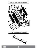
Page 17: ...TROUGH DISPLACEMENT SYSTEM DISPLACEMENT ARM ASSEMBLY TROUGH...
Page 36: ...35...


