28
If you wish to adjust the water level, use the following procedure:
1º
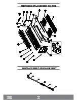
• Stop the movement of the finned axis (50), which will cause the micro gear motor to stop (57).
2º
• Suspend or lower the mobile sensor (55), according to the desired water level.
3º
• 10 seconds after touching the finned axis (50), a new "by pass" cycle will be performed and the
water solenoid valve (63) will be energized for the water to enter the plastic trough (35). After the
water solenoid valve (63) is de-energized, check if the water level is as desired. If contrary, repeat
the operation.
3.3 - FINNED AXIS
The plastic fins (29) have two main purposes:
1ª
• To stir the water for improved efficiency of heat exchange with the cube makers in the
evaporator (20).
2ª
• To control ice thickness.
To replace the finned axis (50), observe the following items:
A • The bearings (41) have a long service life due to the low rotation speed and weight of the
finned axis (50). Even so, they should be checked for wear and tear, and their lubrication.
B • Loosen the screw of the bushing in the micro gear motor connection (45) located near the left
panel (44) of the cylinder head and remove the micro gear motor (57) from the finned axis (50).
C • Loosen the two nuts on the right panel of the cylinder head (34), on the opposite side of the
circuit board (62) and pull it to allow the finned axis (50) to move away from the bearing (41).
FIGURE 1
FIGURE 2
Summary of Contents for EGC 100 A / 150 A
Page 12: ...OVERVIEW EGC 50A COVER COOLING SYSTEM...
Page 14: ...13 I OVERVIEW EGC 150MA I...
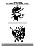
Page 15: ...14 COOLING SYSTEM EGC 50A EGC 75A EGC 100A AND EGC 150A I COOLING SYSTEM EGC 150MA I...
Page 16: ...ELECTRICAL ELECTRONIC PART...
Page 17: ...TROUGH DISPLACEMENT SYSTEM DISPLACEMENT ARM ASSEMBLY TROUGH...
Page 36: ...35...


