29
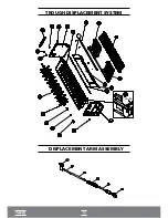
D • Remove the spacers (30) and fins (29) and replace the finned axis (50).
E • During the assembly, mount the spacers (30) and fins (29), placing them between the rows of
the evaporator (20) and push from the left side. Verify if the axes of the evaporator (20), the
stopper of the plastic trough (21), the start-up assembly of the plastic trough (48) and the finned
axis (50) are in the correct position and tighten the two nuts on the panel.
F • Rotate the finned axis (50) manually, before placing the micro gear motor (57) and see if it
works freely. If not, check the alignment of the right (39) and left panel (44) of the cylinder head
(34 and 44), the gap between the bronze bushing (32), any warping on the finned axis (50) or if the
bushing connection on the micro gear motor (45) is misplaced or has excessive wear and tear. If it
does not rotate freely, the micro gear motor (57) will constantly touch the microswitch (59) making
the ice formation cycle come to an early end.
G • In the event of replacing the finned shaft bearings (50), proceed as above.
3.4 - CIRCUIT BOARD
(C) WATER LEVEL SENSOR
(F) MICRO SWITCH
(E) LOWER REED
(D) UPPER REED
(J) GEAR BOX
(L) MICRO GEAR BOX
(H) GAS VALVE
(A) WATER VALVE
FUSE HOLDER
Summary of Contents for EGC 100 A / 150 A
Page 12: ...OVERVIEW EGC 50A COVER COOLING SYSTEM...
Page 14: ...13 I OVERVIEW EGC 150MA I...
Page 15: ...14 COOLING SYSTEM EGC 50A EGC 75A EGC 100A AND EGC 150A I COOLING SYSTEM EGC 150MA I...
Page 16: ...ELECTRICAL ELECTRONIC PART...
Page 17: ...TROUGH DISPLACEMENT SYSTEM DISPLACEMENT ARM ASSEMBLY TROUGH...
Page 36: ...35...


