27
3.1 - DISPLACEMENT SYSTEM AND TROUGH
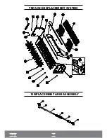
The plastic trough (35) has two stopping points, which are:
Highest Point
Lowest Point
In case there's the need to regulate these points (due to plastic trough (35) replacement, upper or
lower reed switch (54 and 58), magnet displacement system, etc.), proceed as follows:
A •
Highest point
The plastic trough (35) is correctly positioned at the highest point when its edges are touching the
trough stoppers (21) (see Figure 2), and the displacement assembly A and B (see figure 1) is in the
position shown in figure 6. If it is not correct, the adjustment is performed by the magnet's position
(39), (see Figure 4) which is attached to the plastic trough (35) using two oblong screws, allowing
the position to be moved up or down.
C
B •
Lowest point
The plastic trough (35) will be correctly stopped at the lowest point when touching the rear stop
plates in models EGC-50A, EGC-75A, EGC-100A, EGC-150A/EGC-150MA (see figure 3), and
displacement point A as indicated (see Figure 1). If this position is not correct, the adjustment is
done through the reed's position. In the lower switch (58), which is fixated on the left panel using
oblong screws, allowing the position to be moved up or down, see (Fig. 5)
3.2 - ADJUSTMENT OF WATER LEVEL AND ICE CUBE HEIGHT
The minimum height of the ice cube is 25mm and maximum height is 45mm, as seen figure 2. The
height is defined though the mobile sensor (55), see figure 1. For safety reasons, the maximum
water level height should be 5mm below the edge of the plastic trough (35).
STOPPER
TROUGH
Summary of Contents for EGC 100 A / 150 A
Page 12: ...OVERVIEW EGC 50A COVER COOLING SYSTEM...
Page 14: ...13 I OVERVIEW EGC 150MA I...
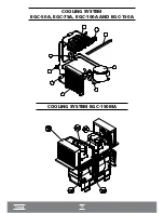
Page 15: ...14 COOLING SYSTEM EGC 50A EGC 75A EGC 100A AND EGC 150A I COOLING SYSTEM EGC 150MA I...
Page 16: ...ELECTRICAL ELECTRONIC PART...
Page 17: ...TROUGH DISPLACEMENT SYSTEM DISPLACEMENT ARM ASSEMBLY TROUGH...
Page 36: ...35...


