21
2 - SYMPTOM PLASTIC TROUGH CANNOT BE LOWERED
Probable causes:
• Gear motor (60) not working
(irreversible defect)
.
• Ice crystals attaching the plastic trough (35) to the evaporator (20)
(reversible defect)
.
• Upper reed switch (54) short circuited
(irreversible defect)
.
When the circuit board (62) switches on the gear motor (60) to lower the trough (35), it monitors
whether the upper reed switch (54) triggers in up to 5 seconds. If this does not happen, the board
understands that there has been an anomaly in the operation. As this is probably a reversible
cause, the circuit board (62) will attempt to normalize the operation, as explained below.
If the cause to this anomaly is ice crystals attached to the plastic trough (35) at the highest point,
the circuit board (62) turns on the gas solenoid valve (28) for 10 minutes. Throughout this period,
it switches on the motor gear (60) for 5 seconds and switches it off for 15 seconds, with the
purpose of detaching the plastic trough (35). In case the operation is normalized within 10
minutes, the cycle will continue regularly. On the contrary, the circuit board (62) switches on the
red LED light to indicates maintenance needs, switches off the gas solenoid valve (28) and the
motor gearfor 10 minutes. After this period, it starts a new attempt at lowering.
3 - SYMPTOM: TROUGH (35) IS LOWERED
BUT DOES NOT REACH THE LOWEST POINT
Probable causes:
• Damage to the displacement system
(irreversible defect)
.
• Gear motor (60) not working
(irreversible defect)
.
• Ice cubes stuck in the lowering grating, blocking the passage of the plastic trough (35)
(reversible defect)
.
• Lower reed switch (58) not working or lacks adjustments
(irreversible defect)
.
The trough has up to 10 seconds to reach its lowest position. When this does not happen, the
circuit board (62) understands that there has been an anomaly in the operation. In an attempt to
normalize the operation, since there is probably a reversible cause, the circuit board (62) switches
on the red LED light which indicates maintenance needs, switches on the gear motor (57) for 10
seconds at every 15 seconds.
After 3 attempts, if the plastic trough (35) does not reach the lowest point, the circuit board (62)
switches on the red LED lights that indicates maintenance needs, switches on the gas solenoid
valve (28) for 45 seconds, cleaning the evaporator (20) from occasional ice cubes. Every 10
minutes, the device repeats this recovery process until the anomaly is solved and the equipment is
inspected. If the plastic trough (35) reaches the highest point, the circuit board (62) will switch off
the red LED light and return to its normal cycle.
Summary of Contents for EGC 100 A / 150 A
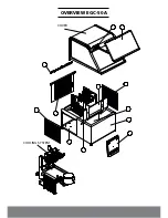
Page 12: ...OVERVIEW EGC 50A COVER COOLING SYSTEM...
Page 14: ...13 I OVERVIEW EGC 150MA I...
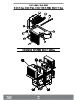
Page 15: ...14 COOLING SYSTEM EGC 50A EGC 75A EGC 100A AND EGC 150A I COOLING SYSTEM EGC 150MA I...
Page 16: ...ELECTRICAL ELECTRONIC PART...
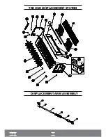
Page 17: ...TROUGH DISPLACEMENT SYSTEM DISPLACEMENT ARM ASSEMBLY TROUGH...
Page 36: ...35...


