22
4 - SYMPTOM: BY-PASS CYCLE OVER 2 MINUTES
Probable causes:
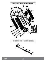
• By-pass gas solenoid valve (28) not
(irreversible defect)
.
• End of cycle microswitch (59) is stuck
(irreversible defect)
.
During the ice detachment cycle, after 45 seconds of by-pass, the circuit board (62) switches on the
micro gear motor (57) for 5 seconds and checks whether the axis is still blocked by any ice cube. If
the finned axis (50) is blocked, the by-pass time is increased in 5 more seconds, as often as needed,
for up to 2 minutes.
If it is not unblocked, the circuit board (62) switches on the red LED light that indicates
maintenance needs, switches off all the components run by the board for 10 minutes and, after
this period, starts another attempt at unblocking.
5 - SYMPTOM: TROUGH (35) IS SUSPENDED,
BUT DOES NOT REACH THE LOWEST POINT
Probable causes:
•
Gear motor (60) not working
(irreversible defect)
.
•
Ice cubes stuck in the plastic lowering grating (4), blocking the passage of the plastic trough (35)
(reversible defect)
.
•
Lower Reed Switch (58) short circuited
(irreversible defect)
.
•
Displacement system spring (31) damaged
(irreversible defect)
.
During the suspension cycle, if the plastic trough (35) does not leave the lowest position within 5
seconds, the circuit board (62) understands that there has been an anomaly in the operation. As
there is probably a reversible cause, the circuit board (62) will attempt to normalize the operation, as
explained below.
The circuit board (62) switches off the motor gear (60) at every 15 seconds and switches it on for a
period of 5 seconds. After 3 attempts, if the plastic trough (35) does not leave its lowest position, the
circuit board (62) switches on the red LED light, switches off the motor gear (60) and waits for 10
minutes. After 10 minutes, the circuit board (62) switches off the red LED light, switches on the gas
solenoid valve (28) for 45 seconds, cleaning the evaporator (20) and preventing the accumulation of
ice crystals in it, and starts another attempt at normalizing the process.
Summary of Contents for EGC 100 A / 150 A
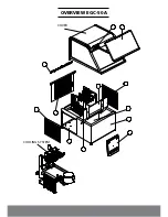
Page 12: ...OVERVIEW EGC 50A COVER COOLING SYSTEM...
Page 14: ...13 I OVERVIEW EGC 150MA I...
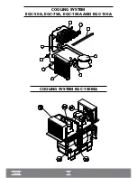
Page 15: ...14 COOLING SYSTEM EGC 50A EGC 75A EGC 100A AND EGC 150A I COOLING SYSTEM EGC 150MA I...
Page 16: ...ELECTRICAL ELECTRONIC PART...
Page 17: ...TROUGH DISPLACEMENT SYSTEM DISPLACEMENT ARM ASSEMBLY TROUGH...
Page 36: ...35...


