en
3. DEFINITION OF PICTOGRAMS
2.4 CLOTHING
The procurement of such personal pro-
tective equipment is the sole responsibil-
ity of the customer or employer.
During machine use and maintenance
operations:
The operator
MUST
always wear suitable
safety shoes, gloves, and hearing protec-
tion devices and wear long, resistant trou-
sers and safety goggles.
Do not wear loose-fitting clothing, jewelry,
ties, scarves, dangling drawstrings that
could get caught by the equipment . Tie up
your hair.
During unpacking and assembly:
The operator
MUST
always wear resistant
safety shoes, gloves, and clothing.
DANGER!
Keep all labels clean and in good condi-
tion, replace them if damaged.
INFORMATION!
2.2
2.2
2.1
2.1
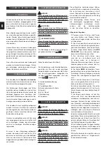
4. TECHNICAL FEATURES
Model
MZP11
MZP12
GROSS and
NET weight
CE declaration label on
the last page
Rated power
Sound power
Acoustic
pressure
Vibrations
Tyres
13x5.00-6
Rotary cutters
diameter
320 mm
Rotary cutters
rotation
275/min
Forward speed
1^
1,1 km/h
Forward speed
2^
-
2,1 km/h
Reverse speed
in 1^
0,96 km/h
Reverse speed
in 2^
-
1,8 km/h
Concerning the engine technical data, please
see the enclosed instructions manual
2 or more people are required to handle
packaging, using the handles on the card-
board box. The GROSS weight is indicated
in the “TECHNICAL FEATURES” chapter.
CAUTION!
Do not overturn or roll the machine. Pos-
sible damage to bonnets and mechanical
parts.
INFORMATION!
If more than one machine or interchange-
able equipment is supplied on pallets,
unload without dropping them on the
ground. Use a forklift if necessary.
5. HANDLING AND PACKAGING
6. UNPACKING/ASSEMBLY
Unpacking
Handlebar support assembly:
secure the handlebar support (B) to the
frame (A), using screws (g) with washers (h)
in the two holes. Secure the knobs (m) with
washers (h), screws (i) and nuts (l) in the slot.
1.3
1.3
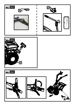
Rotavator assembly:
Insert
the widening tines (C) at the ends of the
other rotavators and secure them with the
screws (n) and nuts (o).
Rotavator cowling assem-
bly:
Unscrew the 6 screws from the seats
on the frame, then position the cowling
(D), taking care to match its slots with the
screw seats, and tighten the 6 screws.
1.5
1.5
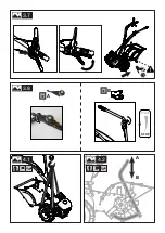
Rotavator cowling bracket
assembly:
Insert the hooks of the bracket
(E), holding this rotated upwards, into the
relevant slots on the Rotavator cowling.
CAUTION: The bracket must be positioned
with the hooks facing the same way as
in the enlargement shown, or rather the
hooks must enter from above into slit “B”
and exit from “A”.
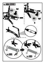
Throttle assembly:
Depending
on the throttle supplied (A, B shown):
-Throttle A: hook terminals “x “ and “y”
of the throttle cables.
-Throttle B: unscrew the screw and nut
from the throttle, then screw back on the
handlebar.
The motor is supplied without lubricating
oil. For information on the type of oil and
quantities to be used, refer to the motor
manual contained in the accessory bag
[F].
1.1
1.1
7. USE
Do not start the engine until all assembly
stages have been completed.
Add lubricating oil to the motor before
first start-up. For information on the type
of oil and quantities to be used, refer to
the motor manual contained in the ac-
cessory bag [F].
1.1
1.1
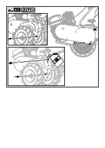
Before starting the machine, check the
oil level inside the motor, as indicated in
1.1
1.1
1.2
1.2
*
1.4
1.4
*
1.6
1.6
CAUTION!
CAUTION!
CAUTION!
CAUTION!
Summary of Contents for MZP 11
Page 3: ...F A 1 1 1 1 g x2 E C i x1 h x4 l x1 m x2 D B o x2 n x2 x2...
Page 4: ...B 1 3 1 3 1 2 1 2 A g l g h h i h h m m o o n n C C A...
Page 5: ...1 4 1 4 D D...
Page 6: ...1 5 1 5 E E E A B...
Page 7: ...8 B 1 6 1 6 1 7 1 7 1 2 3 5 6 7 8 8 9 4 x B x y y A A x x y y x y x A x x y y A B...
Page 10: ...3 1 3 1 10 m 3 3 3 3 OIL FUEL OIL 4 7 4 7 3 2 3 2 3 1 2...
Page 11: ...3 6 3 6 3 5 3 5 3 4 3 4 START STOP A B...
Page 12: ...3 7 3 7 3 8 3 8 START STOP 4 2 4 2 4 1 4 1 A B A B...
Page 13: ...4 4 4 4 35 35 4 3 4 3 4 5 4 5...
Page 14: ...STOP 1 max 0 5 0 STOP 0 0 5 1 max M10 X 0 0 max max max max 2x 4 6 4 6 4 6A 4 6A 4 6B 4 6B...
Page 15: ...4 7 4 7 1 O IL 2 Max oil level 1 1 2...
Page 58: ...el 1 1 1 1 2 CE 1 3 2 1 2 1 1 4 CE CE 2 1 2 1 1 2 3 4 5 6 7 8 2 1 16 2 3 4 5 6 80 7 8 9 10 1...
Page 63: ...el SAE 80 10 6 21 PSI 1 5 bar PSI 11 20 11 10 6 10 4 60 10 5 12 13 7 2 START 1 7 3 10 4 10 4...
Page 64: ...el 14 14 1 2002 95 CE 2002 96 CE 2003 108 CE 14 2 81 08...

