59
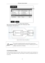
Figure 4.5 Remote Sense Setting Page
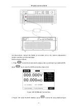
Remote measurement access, please refer to the figure as below.
Wiring Diagram of Remote Sense:
Figure 4.6 Remote-Sense wiring Diagram
If the remote compensation started, the wiring must be the same as above,
otherwise the voltage detection function will be fail. The REMOTE prompt will be
displayed in the status bar of the display.
4.2.2 Shortcut Call Mode
The E-load provides the Shortcut Call function. After the function is enabled, the user can quickly call up
the 10 sets of setup parameters stored in the SAVE (see 4.3) function by directly pressing the 0~9
number keys.
ET System electronic GmbH

