32
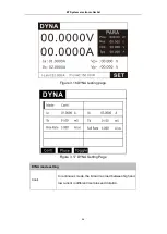
I-range
Choose the appropriate current range according to the real test
condition
Step No.
Select the specified step for parameter setting
Mode
Description
OFF
Empty
CC
CC mode
CV
CV mode
CW
CW mode
CR
CR mode
SHORT
Short
OCP
OCP
EFFT
EFFECT
LED
LED driver source test mode
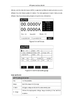
Comparison type setting: AUTO parameter editing interface → comparison type
Curr
Load current, valid in CC/CV/ CP/CR/LED mode
Volt
Input voltage, valid in CC/CV/ CP/CR/LED mode
Pow
Load power, valid in CC/ CV/CP/CR/LED mode
Res
Equivalent resistance, valid in CC/ CV/CP/CR/LED mode
Vpp
Ripple voltage, valid in CC/CV/CP/CR/LED/DYNA mode
Ipp
Ripple current, valid in CC/ CV/ CP/ CR/LED/DYNA mode
OCP
Over-current protection point, valid in OCP mode
Pmax
Maximum output power point, valid in OCP mode
Reg.
Load regulation, valid in Load Effect mode
∆V
Voltage difference between the two loads, valid in Load Effect
mode.
Rs
Power supply series internal resistance, valid in Load Effect mode
Time setting
Different modes have different test time settings
Duration/time
setting
Load time
ET System electronic GmbH


