41
Operation steps:
1.
Press the key
to enter the mode selection page, press the up and down keys to
select BATT, and press the key
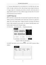
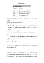
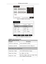
to enter the BATT test interface, as shown in
Figure 3.21.
2.
In Figure 3.21, press the key
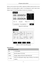
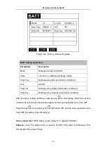
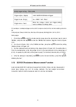
to enter the setting interface, as shown in Figure
3.22.
3.
As shown in Figure 3.22, set the discharge mode to CC mode, current at 1A, stop time
at 0S (when the stop condition is set to 0, it does not participate in the stop judgment.),
the stop voltage at 3V, and the stop capacity at 2.4Ah.
4.
After the setting is completed, press the key
to back to the test interface, press
the key
to start testing.
5.
In the above conditional test, when the battery voltage is lower than 3V, or the
capacity is accumulated to 2.4Ah, the test will stop immediately.
3.8 Short-circuit Simulation Function
The E-load can simulate a short circuit to the source under test. This function is used to
check whether the protection function of the source operated normally under the
short-circuited condition.
Under board operation, press the
key to switch short circuit status.
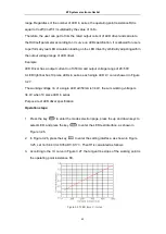
Actual current value consumed by E-load at short circuit depends on the existing current
range of the E-load. The maximum short-circuit current is 110% of current range.
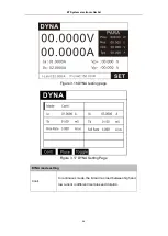
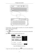
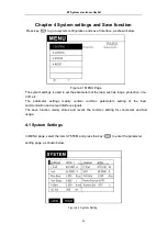
The short circuit test interface is as follows:
ET System electronic GmbH


