background image

56 

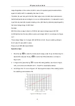
      Figure    4.3 Von

Voff   

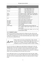
If Von-Delay parameter is set, the E-load will load, when the source voltage reached Von 

and have delayed for Von-Delay time. 

4.1.2 Source Type Selection Function


The E-load has the function of automatically detecting the type of source under test. But 

in some special cases, the source loaded 

dosen’t meet your expectations. you can set 

the corresponding parameters manully according to your source type,and the E-load will 

load it according to the type of source you selected. 

In MENU page, select the SYSTEM item and press the key 

  to enter the parameter 

setting page. Select the source type under test. 

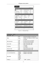
4.2 Configuration 

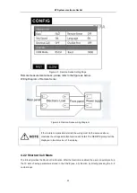
In MENU page, select the item CONFIG and press the key 

to enter the parameter 

setting page, as shown below. 

 ET System electronic GmbH

Summary of Contents for ELP/DCH Series

Page 1: ...1 User s Manual ELP DCH series PROGRAMMABLE DC ELECTRONIC LOAD ET System electronic GmbH 2021 06 10 Manual Edition V 2 2 ...
Page 2: ... 9 LED Simulation Function 42 3 10 SWEEP dynamic frequency conversion scanning 46 3 11 TIMING Time measurement 48 3 12 DCR DC Resistance Measurement Function 50 3 13 Measurement item 52 3 13 1 Voltage current resistance and power measurement 52 3 13 2 Ripple measurement 53 Chapter 4 System settings and Save function 54 4 1 System Settings 54 4 1 1 Von Voff Function 55 4 1 2 Source Type Selection F...

Page 3: ...3 8 2 DB9 77 8 3 Protocol 78 8 4 SCPI Communication Instruction 79 ET System electronic GmbH ...
Page 4: ... same packaging materials used for the delivery to you Check the package contents as follows No Item Quantity 1 Electronic Load 1 2 User s Manual 1 3 RS232 Cable 1 4 Power Cord 1 5 Test Report 1 Safety Notes The instrument is designed to conform to IEC 61010 Safety Standards and has been thoroughly tested for safety prior to shipment However using the instrument in a way not described in this manu...

Page 5: ...r or moderate injury to the operator or damage to the instrument or malfunction Indicates functions of the instrument or relative suggestion of a correct operation Usage Notes Installation environment Operating temperature and humidity range 0 C 40 C 80 RH no condensation Storage temperature and humidity range 23 5 C 80 RH no condensation Installing the instrument in inappropriate locations may ca...

Page 6: ...ution Contact your authorized Hopetech distributor or reseller in this case Handling Precautions Do not try to modify disassemble or repair the instrument This may result in fire electric shock accident or injury Do not place the instrument on an unstable or slanted surface It may drop or fall causing injury or instrument failure This equipment is an electric energy conversion to heat equipment bl...

Page 7: ...st lead correctly Wear gloves of rubber or similar materials during measurement For achieving the measurement accuracy it is recommended that the equipment should be operated half an hour after power on ET System electronic GmbH ...

Page 8: ...8 Chapter 1 Size and Installation 1 1 Dimension ELP DCH series electronic load dimension Figure 1 1 Appearance of instrument ET System electronic GmbH ...
Page 9: ...9 Figure 1 2 Instrument dimension 1 Figure 1 3 Instrument dimension 2 ET System electronic GmbH ...
Page 10: ...g the gap it can be used for cabinet installation and positioning 1 3 Plug in Power Cord Connect an appropriate IEC power cord to the DC Load and plug the power cord into an AC power outlet Please find the following power cord type in different countries and areas Ensure that the line voltage selector switch on the back panel is set to match your line voltage Failure to do so could result in damag...

Page 11: ...functions ELP DCH series E load is mainly used for battery AC DC DC DC modules chargers and electronic components and other product performance testing It provides a best solution for design development and production line testing ELP DCH series E load supports RS232 RS485 and Ethernet communication interfaces to fit your versatile solution and testing needs 2 2 Features 1 24 bit true color LCD di...

Page 12: ...eed dynamic frequency conversion scanning function SWEEP 10 Short circuit mode SHORT 11 Shortcut mode supports 10 sets of global data storage and reading SHORTCUT 12 No loading mode OFF 13 Support Von and Voff functions 14 Remote compensation measurement mode REMOTE 15 Memory capacity up to 200 8 groups 16 Intelligent fan system fan automatically initiated activate according based on changing to t...

Page 13: ...the front panel for the ELP DCH E Load All models have the same front panel only the terminal section will vary based on the model Figure 2 1 front panel Item Description 1 Warning lights for loading failure or other warning states 2 U disk interface 3 Power up key 4 Function keys 5 E Load input terminal 6 Operating keys 7 Digital keys 8 Operating keys 9 LCD display panel ET System electronic GmbH...

Page 14: ...witch the interface between load system configuration system parameter setting and loading the setting files In the working mode interface adjust the cursor position and adjust the loading value Move the status bar position on another interface Trigger the E load in specific working mode Confirm the selected value or enter the setting menu Cancellation of operation or moving back to the top menu L...

Page 15: ...n function is turned on Through the SENSE port at the rear panel of E load the output voltage of the power supply under test is collected Using remote sensing you can sense the voltage at the power supply s terminals effectively removing the effect of the voltage drop in the connection wire Loading automatically while start setup voltage VON voltage Stop loading while shutdown voltage Voff voltage...

Page 16: ...ale current corresponding to 0 10V output can be connected to the oscilloscope 3 Hardware Power button 4 Power inlet AC 100 240V input 5 LAN communication port 6 SENSE port for voltage sense compensation 7 DB9 communication interface RS232 485 8 I O interface connector this I O interface need to be powered by external power 2 6 First turn on checkout The successful self test process indicates that...

Page 17: ...itive and negative polarities of E load during connection 2 6 1 Self test Process The standard E load self test process is as follows 1 Connect an appropriate IEC power cord to the E load and plug the power cord into an AC power outlet Press the hardware power button at the back panel At this time soft power switch button lights up red in the front panel long press the soft power switch to power o...

Page 18: ... connected 2 Check the hardware Power button at the back panel in ON state and the soft Power Switch at the front panel is lit red if the E load using soft power switch button Go to step 3 YES Press the Power button to turn on the instrument and to see if the exception is cleared NO 3 Check whether the voltage of power supply is larger than the rated voltage of the equipment ET System electronic G...

Page 19: ...DYNA dynamic test function BATT battery test function SHORT short circuit simulation function LED load simulation function SWEEP dynamic frequency conversion scanning function TIMEING time measurement function DCR DC resistance measurement function Measurement items 3 1 Basic Operation Modes The E load has four basic modes 1 Constant current mode CC 2 Constant voltage mode CV 3 constant resistance...

Page 20: ...e In CC mode the E load provides two methods to set the constant current value 1 In CC mode use the numeric keys to input the current value press the key to confirm the setup constant current value and press the key to load or unload the source 2 Press the key to move the cursor position and press the key to adjust the value at the corresponding position ET System electronic GmbH ...
Page 21: ... load provides two methods to modify the constant voltage value 1 In CV mode use the numeric keys to input the voltage value press the key to confirm the setup constant voltage value press the button to ON OFF the loading test 2 Press the key to move the cursor position and press the key to adjust the value at the corresponding position ET System electronic GmbH ...

Page 22: ...nges Figure 3 3 CR mode In CR mode the E load provides two methods to set the constant resistance value 1 In CR mode use the numeric keys to input the resistance value press the key to confirm the setup constant resistance value and press the key to on off the loading test 2 Press the key to move the cursor position and press the key to adjust the value at the corresponding position ET System elec...

Page 23: ... to set the constant power value 1 In CW mode use the numeric keys to input the power value press the key to confirm the setup constant power value and press the key to on off the loading test 2 Press the key to move the cursor position and press the key to adjust the value at the corresponding position In CW mode the working loop of the instrument can be modified see parameter settings I V V2 V3 ...

Page 24: ...d the LIST function will form a variety of complex sequences by editing step value time and slope of each step to meet complicated test requirements LIST parameters comprise designation of input list file input step count 200 steps at maximum step time 10uS 50S as well as setting value and slope of each step The list file can be stored in non volatile RAM available for a quick output in case of us...

Page 25: ...it receives a trigger signal the load will start List operation for CNT cycles till completion CNT parameters can be set from 1 9999999 STEP Step mode when it receives a trigger signal the E load will perform the next step according to the next setting parameter in the list file When setting the parameters press the key ADD to add one step press the key DELE to delete one step press the key PREV t...

Page 26: ...ess the up and down keys to select LIST and press the key to enter the LIST test interface 2 In Figure 3 5 press the key to enter the setting interface as shown in Figure 3 6 3 Select the desired file number by pressing the key as shown in Figure 3 6 4 Use the up down left and right direction keys to select the mode as CONT the counting function only valid in CNT mode 5 Set the first step current ...

Page 27: ...time check the E load input voltage and judge whether it is higher than standard voltage value If higher it indicates that OCP does not occur Repeat current stepping operation till the E load operates to the cutoff current If the input voltage is always greater than the OCP trigger voltage OCP does not occur When the input voltage is lower than the OCP trigger value OCP occur and test terminated A...

Page 28: ...s the up and down keys to select OCP and press the key to enter the OCP test interface 2 In Figure 3 8 press the key to enter the setting interface as shown in Figure 3 10 Use the up down left and right direction keys to set the parameters as shown in Figure 3 10 OCP parameter Istart Start Current Iend End Current Step Steps 1 1000 Dwell Step duration 0 01 999 99 V trig Trigger voltage level Ocp L...

Page 29: ...ion EFFT test function its principle shown in the figure below The load will be carried by three different load mode Imin Inormal Imax Each loading time continues for a preset time Delay then record voltage values in different load mode According to the following formula finally calculated the load regulation the maximum differential pressure ΔV and the internal resistance Rs of the power supply Δ...

Page 30: ...rrent at 3A delay value at 0 5S 4 The E load will carry the three setup currents separately record the corresponding voltage value and calculate ΔV Rs Reg Observe whether the Reg test value meets the design requirements 3 5 Auto test function Auto test function is used for product inspection of the production line The load current is loaded and tested sequentially according to the steps edited in ...

Page 31: ...ee the corresponding chapters of each mode Introduction Figure 3 12 AUTO test Figure3 13 AUTO test editing page Auto test file list AUTO setting parameters File 1 8 file available Steps Each file allows 0 to 50 steps V Start A trigger voltage value start to automatically load V range Choose the appropriate voltage range according to the real test condition ET System electronic GmbH ...

Page 32: ... CP CR LED mode Pow Load power valid in CC CV CP CR LED mode Res Equivalent resistance valid in CC CV CP CR LED mode Vpp Ripple voltage valid in CC CV CP CR LED DYNA mode Ipp Ripple current valid in CC CV CP CR LED DYNA mode OCP Over current protection point valid in OCP mode Pmax Maximum output power point valid in OCP mode Reg Load regulation valid in Load Effect mode V Voltage difference betwee...

Page 33: ... Output conditions Pass Start trigger output TRO when the test passed Fail Start trigger output TRO when the test failed End Start trigger output TRO when the test ended Disable Disable trigger output Fail action Cont Continue to complete all measurements when the single step detection item is judged to be unqualified Abort The auto test is terminated immediately when the single step item is judge...

Page 34: ...next step 9 Select step N using numeric keys to set steps and set the 2nd step 10 Mode setting select OCP mode set start current to 3A and end current to 6A Select compare type at OCP set upper limit value to 5 2 lower limit value to 4 8 step time to 0 1S trigger level to 1V refer to Chapter 3 3 for details 11 Set the unloading time The power supply stops output after over current occurred We here...

Page 35: ...between the two load currents This function is usually used to test dynamic characteristics of the source The principle is shown in the figure below The E load loaded the source with the current Ib for Tb time interval and then according to the setting flow rate The load current drops to the Ia load in setting flow rate and the entire drop time and the Ib load duration are Tb Then the load current...

Page 36: ...e 3 16 DYNA testing page Figure 3 17 DYNA Setting Page DYNA mode setting Conti In continuous mode the E load can load between high and low current in different rise rates and duration ET System electronic GmbH ...

Page 37: ...tting parameters Parameter Description Ia Low level loading current Ta Low level current duration setting range 10uS 50S Ib High level loading current Tb High level current duration setting range 10uS 50S Rise Rate Current rise time rate A uS Fall Rate Current fall time rate A uS Mode Continuous Pulse Toggle Continuous mode In continuous mode and dynamic function enabled the E load continuously sw...

Page 38: ...t of every trigger signal Figure 3 20 DYNA trigger mode Trigger control When the dynamic test mode is set to pulse mode or trigger mode the trigger control is activated The trigger mode has 3 types 1 Button trigger Trigger once when the TR button is pressed once 2 External hardware input trigger Trigger when TRI terminal level in the rear panel of the E load is continuously at a low level of 5mS o...

Page 39: ...de to continuous test high current Ib 3A high time Tb 1mS low current Ia 1A low time Ta 1mS rise fall rate 3A uS 4 After the above settings are completed press to return the test interface and press to start the test 5 Observe the values of Vp and Vp during the test 3 7 Battery test function The CC CP and CR mode can be applied for battery capacity test with discharge conditions Discharging time a...

Page 40: ...mination conditions After the above setting confirmed press the key to start testing When the set stop conditions is reached the test will be stopped and the load input status turn to be OFF Press the key to stop testing the light wil be OFF and the load input status turns to be OFF the battery stops discharging Source under test 18650 battery rated voltage 3 7V capacity 2400mAh Purpose check the ...

Page 41: ...o back to the test interface press the key to start testing 5 In the above conditional test when the battery voltage is lower than 3V or the capacity is accumulated to 2 4Ah the test will stop immediately 3 8 Short circuit Simulation Function The E load can simulate a short circuit to the source under test This function is used to check whether the protection function of the source operated normal...

Page 42: ...oad front panel to select the LED function to switch the LED working state The LED equivalent circuit is as follows Figure 3 24 LED I V curve Io rated working current which should be set as the rated current of measured LED driver Vo rated working voltage which can be set as any value of output voltage range of the ET System electronic GmbH ...
Page 43: ...alent to the resistor Rd and the power source Vf in series Its I V curve is equivalent to the tangent of the true LED nonlinear VI curve at the operating point Vo Io as shown in Figure 3 24 Vo Vf Io Rd formula 3 1 Let Vf a Vo a 1 Vo a Vo Io Rd Rd 1 a Vo Io Let coeff Rf 1 a That is Rd Rf Vo Io a 1 Rd Io Vo formula 3 2 By checking LED specification to know Vo Io and Rd a can be calculated by formula...

Page 44: ...is as follows The actual load value is loaded according to the following formula Vx 1 Coeff Vo Ix Coeff Vo Io Vx The output voltage of the LED driver under actual load adjustment Ix The output current of the LED driver under actual load adjustment Set different Vo Io and Rf the calculation above will bring different data Figure 3 26 LED mode testing page Parameter calculation The users need to set...

Page 45: ...ght bar has 10 piece LEDs in series each single LED I V curve showed in Figure 3 27 The working voltage Vo of a single LED at 350mA is 3 44V the sum working voltage is 34 4V when 10 piece LED in series Purpose test LED driver specification Operation steps 1 Press the key to enter the mode selection page press the up and down keys to select LED and press the key to enter the LED test interface as s...

Page 46: ... each current level will be determined by the sweep frequency and duty cycle Duty At the same time the scanning frequency will also gradually increase from the starting scanning frequency Fstart to the cutting frequency Fend the step frequency is Fstep and the scanning duration of each frequency point is single frequency time Dwell during the scanning process the input voltage will overshoot and f...

Page 47: ...h current Imax High level load current Starting frequency Fstart Initial scan frequency 0 01Hz 50KHz Cut off frequency Fend Cut off scan frequency 0 01Hz 50KHz Step frequency Fstep Step frequency 0 01Hz 50KHz Single frequency time Dwell Single frequency point duration 0 001S 99 999S Duty cycle Duty Duty cycle 1 99 Rising rate Current rise rate 0 3 ET System electronic GmbH ...
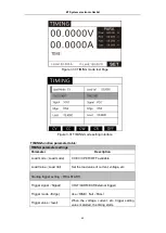
Page 48: ...r 0 1S stepping of 10Hz In this way the load will stop to be carried until the frequency reaches 1000Hz 4 After the setting is completed press to exit to the test interface press the key to start stop the test 3 11 TIMING Time measurement The E load provides time measurement function with an accuracy of 0 1mS Under the predetermined load condition the E load automatically captures 2 trigger signal...

Page 49: ...Load mode Load mode CC CV CP CR OFF available Load Value Load Val Set the load value of current voltage etc Starting trigger setting TRIG START Trigger signal Signal VOLT CURR EXT External trigger Trigger mode Edge rise RISE fall FALL Trigger value level When the voltage current etc trigger setting value is started the timing starts ET System electronic GmbH ...

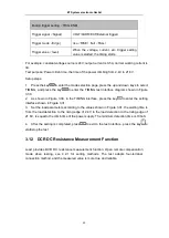
Page 50: ...2 As shown in Figure 3 30 in the TIMING interface press the key to enter the setting interface shown in Figure 3 31 3 Set the load parameters according to the values shown in Figure 3 31 the waiting time is from the load detection to the rising edge of 2 4V to the load detection to the rising edge of 21 6V is equal to the climb time of the power supply The minimum detection time is 100uS 4 After t...

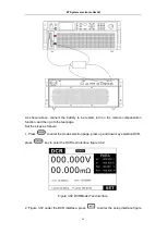
Page 51: ...e test page Set the steps as follows 1 Press to enter the mode selection page press up and down key selection DCR press key to enter the DCR test interface figure 3 32 Figure 3 32 DCR Model Test Interface 2 Figure 3 32 under the DCR interface press to enter the setup interface figure ET System electronic GmbH ...

Page 52: ...er ripple voltage Vpp and ripple current Ipp 3 13 1 Voltage current resistance and power measurement The E load display the average voltage value and the average current value in real time at measurement page The maximum measurement bandwidth is 250kHz and accurate measurement can also be realized under large ripple conditions The E load provides two measurement rates fast and slow In the harsh co...

Page 53: ...more accurate and has extremely high repeatability However the traditional measurement method will cause the switch ripple to be attenuated due to the capacity of electrolytic capacitor and the cable The difference of capacity result in varying degrees of attenuation has both large errors and poor repeatability In general the ripple contains two different frequency bands of the power frequency rip...

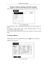
Page 54: ...ange protection Von Voff etc The parameter settings mainly contain common parameters setting of the load communication and output interface signals The save function mainly stores and recalls the common setting for convenient and fast usage 4 1 System Settings In MENU page select the item SYSTEM and press the key to enter the parameter setting page as shown below Figure 4 2 System Setting ET Syste...

Page 55: ... the power product may latch protection In this case you d batter set Von on Then E load will load when power voltage is higher than this value by setting VON value Please confirm the necessity of setting loading voltage this step provides convenience for limiting working voltage value of the source under test If no necessary don t set the loading voltage without authorization to prevent unnecessa...

Page 56: ...cial cases the source loaded dosen t meet your expectations you can set the corresponding parameters manully according to your source type and the E load will load it according to the type of source you selected In MENU page select the SYSTEM item and press the key to enter the parameter setting page Select the source type under test 4 2 Configuration In MENU page select the item CONFIG and press ...

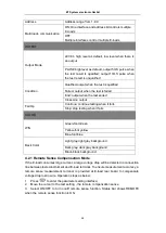
Page 57: ...nse function OFF ON Remote sense function ON Key sound OFF Key sound function OFF ON Key sound function ON Language EN In English CN In Chinese Shortcut Call OFF Shortcut call function OFF ON Shortcut call function ON Communication Set Communication Mode RS232 RS232 Communication RS485 RS485 Communication Baud Rate 9600 19200 38400 57600 Protocol SCPI SCPI protocol ET System electronic GmbH ...

Page 58: ...p testing when it fails COLOR WIN Green font Green Yellow font yellow Blue font blue Back Color Light gray light gray background Dark gray dark gray background Black black background 4 2 1 Remote Sense Compensation Mode If the E load consumes large current a large voltage drop will be detected in connection line between tested instrument and E load terminal To ensure measurement accuracy a remote ...

Page 59: ...ng must be the same as above otherwise the voltage detection function will be fail The REMOTE prompt will be displayed in the status bar of the display 4 2 2 Shortcut Call Mode The E load provides the Shortcut Call function After the function is enabled the user can quickly call up the 10 sets of setup parameters stored in the SAVE see 4 3 function by directly pressing the 0 9 number keys ET Syste...

Page 60: ... example set the output mode to Level the output condition to Qualified and failed action to Stop The TRO port level will change from high to low when the test is qualified and will remain the status until the next test begins If a failure is encountered the output is always high and the test is stopped For more specific settings refer to Chapter 4 2 Parameter Settings Output and Chapter 6 1 I O P...

Page 61: ... a quick call function that is In Menu page select the item CONFIG TEST SETTING SHORTCUT CALL as shown in Figure 4 8 after the shortcut call enabled you can directly use the 0 9 number keys to call the test file in the SAVE 1 9 corresponds to file No 1 9 and 0 corresponds to file No 10 At this time the number key has only a shortcut call function and no data input function If you need to restore t...

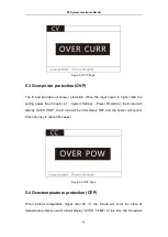
Page 62: ...switch to OFF status The E load LCD will display OTP and the WARNING indicator lights up 5 1 Over voltage protection OVP The E load provides overvoltage protection When the input voltage is higher than 110 of the rated voltage the E load will display OVER VOLT the E load will be immediately OFF and the buzzer will sound Press any key to cancel the beeper Figure 5 1 OVP Page 5 2 Over current protec...

Page 63: ...er Protection the E load will display OVER POW the E load will be immediately OFF and the buzzer will sound Press any key to cancel the beeper Figure 5 3 OPP Page 5 4 Over temperature protection OTP When internal temperature higher than 80 C the E load will enter the state of temperature protection and LCD will display OVER TEMP At this time the E load will ET System electronic GmbH ...

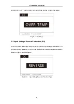
Page 64: ...Voltage Reverse Protection RV When the polarity of the input voltage is reversed the E load will display REVERSE the E load will be immediately OFF and the buzzer will sound until the wiring is disconnected press any key to cancel the beeper Figure 5 5 Input Voltage Reverse Protection Page ET System electronic GmbH ...

Page 65: ...and other control units to complete the automatic test 6 1 I O Interface Figure 6 1 I O interface 1 EXV external power supply interface 2 GND ground 3 EOC test completion signal output 4 TRO trigger signal output port 5 TRI trigger signal input port 6 2 I O Interface Function The port circuit diagram is as follows ET System electronic GmbH ...

Page 66: ...etes EOC outputs low level 4 The TRO is the trigger output port In the modes like AUTO OCP which needs to judge the output mode can be set to output the signal required by the user for the user to connect to other devices For specific settings please refer to the parameter settings in Chapter 4 2 Output 5 The TRI is the trigger input port When the TRI port is connected to the low level short circu...

Page 67: ...urrent 100us 100us 100us CV mode Range 15V 150V 50V 500V 15V 150V Resolution 0 2mV 2mV 0 7mV 7mV 0 2mV 2mV Accuracy 0 05 0 025 FS CC mode Range 24A 240A 12A 120A 50A 500A Resolution 0 3mA 3mA 0 1mA 1mA 0 7mA 7mA Accuracy 0 1 0 1 FS CR mode Range 0 1Ω 7 5kΩ 0 1Ω 7 5kΩ 0 1Ω 7 5kΩ Resolution 16Bits Accuracy 0 1 CW mode Range 4000W Resolution 16Bits Accuracy 0 2 0 2 FS Dynamic mode Ta Tb 10us 50s Mini...

Page 68: ...ion Size length width height 624mm 483mm 177mm Weight Kg 39kg Model HP8502 HP8502B HP8502C Input voltage 15V 150V 50V 500V 15V 150V Input current 24A 240A 12A 120A 50A 500A Input power 5000W Mini operating voltage 1V 240A 2 5V 120A 1 5V 500A Mini rise time at full scale current 100us 100us 100us CV mode Range 15V 150V 50V 500V 15V 150V Resolution 0 2mV 2mV 0 7mV 7mV 0 2mV 2mV Accuracy 0 025 0 05 F...

Page 69: ...mA 0 9mA 0 3mA 3mA Accuracy 0 05 0 05 FS Read back Ripple Range R I 150V 240A 500V 120A 150V 500A bandwidth 10Hz 250kHz Accuracy 1 Protection range Overpower protection 5250W Overcurrent protection 252A 126A 525A Overvoltage protection 158V 525V 158V Over temperature protection 85 Specification Size length width height 624mm 483mm 177mm Weight Kg 44kg Model HP8602 HP8602B HP8602C Input voltage 15V...

Page 70: ...Accuracy 0 2 0 2 FS Dynamic mode Ta Tb 10us 50s Minimum resolution 10us Maximum up down slope 2 5A us 1A us 5A us Read back voltage Range 15V 150V 50V 500V 15V 150V Resolution 0 1mV 1mV 0 3mV 3mV 0 1mV 1mV Accuracy 0 025 0 025 FS Read back current Range 24A 240A 12A 120A 50A 500A Resolution 0 1mA 1mA 0 09mA 0 9mA 0 3mA 3mA Accuracy 0 05 0 05 FS Read back Ripple Range R I 150V 240A 500V 120A 150V 5...

Page 71: ...0V 50V 500V 15V 150V Resolution 0 2mV 2mV 0 7mV 7mV 0 2mV 2mV Accuracy 0 05 0 05 FS CC mode Range 24A 240A 12A 120A 50A 500A Resolution 0 3mA 3mA 0 1mA 1mA 0 7mA 7mA Accuracy 0 05 0 05 FS CR mode Range 0 1Ω 7 5kΩ 0 1Ω 7 5kΩ 0 1Ω 7 5kΩ Resolution 16Bits Accuracy 0 2 CW mode Range 8000W Resolution 16Bits Accuracy 0 2 0 2 FS Dynamic mode Ta Tb 10us 50s Minimum resolution 10us Maximum up down slope 2 ...

Page 72: ...ELP DCH8103C ELP DCH8123B ELP DCH8123C Input voltage 50V 500V 15V 150V 50V 500V 15V 150V Input current 24A 240A 50A 500A 24A 240A 50A 500A Input power 10kW 12kW Mini operating voltage 1 5V 240A 1 5V 500A 2 5V 240A 1 5V 500A Mini rise time at full scale current 100us CV mode Range 50V 500V 15V 150V 50V 500V 15V 150V Resolution 0 7mV 7mV 0 2mV 2mV 0 7mV 7mV 0 2mV 2mV Accuracy 0 05 0 05 FS CC mode Ra...

Page 73: ...pple Range R I 500V 240A 150V 500A 500V 240A 150V 500A bandwidth 10Hz 250kHz Accuracy 1 Protection range Overpower protection 10500W 12600W Overcurrent protection 252A 525A 252A 525A Overvoltage protection 525V 158V 525V 158V Over temperature protection 85 Specification Size length width height 624mm 483mm 8U Weight Kg 105Kg 115Kg Model ELP DCH8143B ELP DCH8143C ELP DCH8163B ELP DCH8163C Input vol...

Page 74: ...mum resolution 10us Maximum up down slope 2 5A us 5A us 2 5A us 5A us Read back voltage Range 50V 500V 50V 500V 50V 500V 15V 150V Resolution 0 3mV 3mV 0 1mV 1mV 0 3mV 3mV 0 1mV 1mV Accuracy 0 025 0 025 FS Read back current Range 24A 240A 50A 500A 24A 240A 50A 500A Resolution 0 1mA 1mA 0 3mA 3mA 0 1mA 1mA 0 3mA 3mA Accuracy 0 05 0 05 FS Read back Ripple Range R I 500V 240A 150V 500A 500V 240A 150V ...

Page 75: ...05 0 05 FS CC mode Range 24A 240A 50A 500A 24A 240A 50A 500A Resolution 0 3mA 3mA 0 7mA 7mA 0 3mA 3mA 0 7mA 7mA Accuracy 0 1 0 1 FS CR mode Range 0 1Ω 7 5kΩ 0 1Ω 7 5kΩ 0 1Ω 7 5kΩ 0 1Ω 7 5kΩ Resolution 16Bits Accuracy 0 2 CW mode Range 18kW 20kW Resolution 16Bits Accuracy 0 2 0 2 FS Dynamic mode Ta Tb 10us 50s Minimum resolution 10us Maximum up down slope 2 5A us 5A us 2 5A us 5A us Read back volta...

Page 76: ...curacy 1 Protection range Overpower protection 18900W 21000W Overcurrent protection 252A 525A 252A 525A Overvoltage protection 525V 158V 525V 158V Over temperature protection 85 Specification Size length width height 624mm 483mm 12U 624mm 483mm 16U Weight Kg 165Kg 195Kg ET System electronic GmbH ...

Page 77: ...o communicate with a computer for selection including RS232 RS485 and LAN i Press any key on any work interface to enter the parameter setting interface ii Press the left or right button to move the cursor to the communication mode box under the communication setting bar iii Select the RS232 RS485 LAN communication mode at the bottom of the screen 8 2 DB9 Figure 6 1 DB9 pins of plug GND RS232 TXD ...

Page 78: ...ace Ii Press the left or right button to move the cursor to the address box under the Communication setting bar Iii Press the number keys to edit After editing press ENTER to confirm the operation Please note that this address should be an integer between 0 and 99 Select the Baud rate i Press the key on any working interface to enter the parameter setting interface Ii Press the left or right butto...

Page 79: ...Back no 3 INPut Meaning input on or off 0 off 1 on Example Input on Send INPut 1 Back no 4 CURRent RANGe Meaning set current range LOW HIGH 0 1 Example set low current range Send CURRent RANGe 0 Back no 5 VOLTage RANGe Meaning set the voltage range LOW HIGH 0 1 Example set the voltage range to LOW Send VOLTage RANGe 0 Back no 6 CURRent SLEW Meaning set current rise time and fall time Example set t...

Page 80: ...Tection 3 Back no 10 POWer PROTection Meaning set power protection value Example set power protection value to 150W Send POWer PROTection 150 Back no 11 VOLTage ON Meaning set Von value Example set the start voltage value to 10V Send VOLTage ON 10 Back no 12 VOLTage OFF Meaning set the Voff value Example set the shutdown voltage value to 5V Send VOLTage OFF 5 Back no 13 MODE Meaning set working mo...

Page 81: ...the CV working mode voltage to 10V Send VOLTage 10 Back no 16 POWer Meaning set the power value in CW mode Example Set the CW working mode voltage to 100W Send POWer 100 Back no 17 RESistance Meaning set the resistance value in CR mode Example Set the CR working mode voltage to 1000Ω Send RESistance 1000 Back no 18 MEASure VOLTage Meaning read measured voltage value Example read measured voltage v...

Page 82: ...rent range Send CURRent RANGe Returns 0 1 23 VOLTage RANGe Meaning read the voltage range Example read the voltage range Send VOLTage RANGe Returns 0 1 24 CURRent SLEW RISE Meaning read the current rise time Example read the current rise time Send CURRent SLEW RISE Returns 00 0000 25 CURRent SLEW FALL Meaning read the current fall time Example read the current fall time Send CURRent SLEW FALL Retu...

Page 83: ...ing set the duration for high level loading current in dynamic mode Example set the duration 5mS for high level loading current in dynamic mode Send DYNamic HIGH DWELl 5 Back no 30 DYNamic LOW Meaning set low level loading current in dynamic mode Example set low level loading current at3A in dynamic mode Send DYNamic LOW 1A Back no 31 DYNamic LOW DWELl Meaning set the duration for low level loadin...

Reviews: