34
current 3A.
Purposes:
to test comprehensive performance of power supply
1. Load capacity test: 3A normal current, to compare voltage within range of 23.5~24.5V.
2. Over-current protection test: use OCP mode to test if the power supply over-current point
within the range of 4.8~5.2A.
3. Load effect test: use EFFT mode to test if the load effect of the power supply is within 0.5%.
4. Judgment qualified: output level signal when the test fails.
Operation steps:
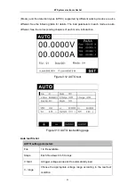
1.
Press the key
to enter the mode selection page, press the up and down keys to
select AUTO, and press the key
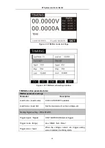
to enter the AUTO test interface, as shown in
Figure 3.12.
2.
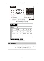
In Figure 3.12, press the key
to enter the setting interface, as shown in Figure 3.13.
3.
Select the file 1 by pressing the key + /-, set the steps to 3.
4.
Set auto trigger level to 5V. After using ON/OFF to start test for the first time, in the future,
when load detects an input voltage greater than 5V, the load will automatically turn on the
ON/OFF function.
5.
Select step N, using numeric keys to set steps, and set the 1st step first.
6.
Mode setting, select CC mode, and set the load value at 3A.
7.
Compare type and voltage, to set upper limit to 24.5V and lower limit to 23.5V.
8.
Set the load time to 1S, test delay to 0.5S, and unloading time to 0S, that is, no unloading
delay required, and directly start loading the next step.
9.
Select step N, using numeric keys to set steps, and set the 2nd step.
10.
Mode setting, select OCP mode, set start current to 3A and end current to 6A;
Select compare type at OCP, set upper limit value to 5.2, lower limit value to 4.8, step
time to 0.1S, trigger level to 1V, refer to Chapter 3.3 for details.
11.
Set the unloading time. The power supply stops output after over-current occurred. We
here set the unloading time to 1S (different power supplies have different protection
recovery time, it is allowed to set unloading time), start to the next step until the power
supply restore to output.
12.
Select step N, using numeric keys to input 3 to set the 3rd step.
13.
Mode setting, select EFFT mode, set min current to 0A and max current to 5A, normal
current to 3A;
Select compare type at Reg., set upper limit value to 1, lower limit value to 0(0~1%),
Set test time to 1S, delay to 0.5S, and unload delay to 0 (that is, each current load time is
1S, and test and compare the data after 0.5S at each step),refer to Chapter 3.4 for
details.
14.
press the key
to return the test interface after set the 3 test steps.
15.
Output level signal when test result is unqualified. Test interface → press
key →
system setting → press
key → press the up and down keys to select the output item.
Refer to Chapter 4.2 for how to set the parameters in details.
16.
Set the output mode to level, output condition to unqualified, and failed action to stop.
This means, when the test result is unqualified, the TRO port outputs a low level signal.
ET System electronic GmbH


