ESKA ERG-H5 Installation Use And Care Manual Download Page 8


  Page 

8

 of 

32


While connecting the product to the line; place it in such way that the product shall not block the front of the sensing line. Pay attention 
to the specified distance of the measuring point for the sensing line. While connecting the product to the line; use appropriate wrenches 
for tightening inlet and outlet connections and make sure that no excessive load, force and impact is applied and that external leakage 
is prevented. Pipe connections should always be welded to the upper part of the pipe, and the hole in the pipe should not show any burrs 
or protrusions inwards.  Ensure that there is no pressure gas trapped in the line where the product will be installed and between the line 
and the product, that the gas supply is turned off and that the possibility of opening is completely prevented. After tightening, make the 
controls  that  the  connections  are  fully  seated  in  the  sockets  and  there  are  no  cracks,  breakages,  etc.,  mechanical  problems  and 
deformations in the connections and in the product and that no mechanical stress caused by the line, pipe and connection has occurred. 
If connection components which are larger than the connection diameter on the body of the product are installed in the inlet and outlet 
of the product for assembly, forces and moments exceeding the values required by the main connection diameter on the body should 
not be applied and limitations should not be exceeded. 

While screwing the product on the line, make sure that the pipe thread is not too long in order to prevent damage on the body. If the 
product is modularly flanged; make sure that the inlet and outlet counter flanges are perfectly coaxial and parallel in order to avoid 
unnecessary  mechanical  pressure  on  the  product  body.  Also  calculate  the  space  required  to  place  the  seal.  As  the  product  may  be 
disassembled from the installation for testing, repair, maintenance, replacement and similar purposes, use a gland or ball valves at the 
product inlet and outlet. Connect the product to the line without causing mechanical stress. It should be remembered that excessive 
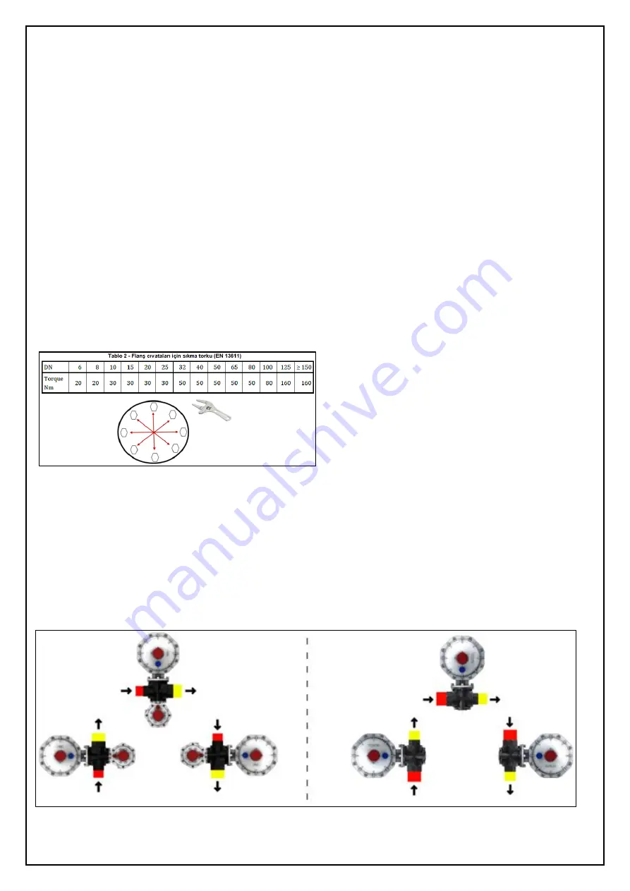
loads to be applied to the body may lead to cracks. For these reasons, assemble with wrenches. For products with flanges, follow the 
mounting  torques  shown  in  chart  2. For  tightening operations,  make  available  single  or  double  calibrated  torque  wrenches  or  other 
controlled locking tools. After tightening, make the controls that the connections are fully seated in the sockets and there are no cracks, 
breakages, etc., mechanical problems and deformations in the connections and in the product and that no mechanical stress caused by 
the line, pipe and connection has occurred. 


The necessary gaps and spaces should be left around the product and between the wall and the product by taking the outer dimensions 
of the product as reference, in order to enable access 

to the product’s 

components, perform the necessary operations and carry out 

testing. If the product is accessible to unauthorized persons, provide protection against impact or accidental contact. During installation, 
make sure that the gas in front of the product is turned off. Close the gas cutting valves at the line inlet and outlet. Make sure there are 
no gas flows. While mounting the product on the line; connection shall be in the direction of the arrow indicated on the product. The 
arrow on the product shall be mounted in such way that the outlet side shall indicate the user, that means it shall show the gas flow 
direction. By this, the flow will be from the network to the user. 
- Install the product in horizontal or vertical position with a tolerance of ±5

o

C at the appropriate mounting position as shown in figure 3. 

However, it should be preferred to install in such way that the cover shall be vertical with an upwards direction. The mounting position 
for  dry gases  may  be  vertical  or  horizontal  provided  that  the  outlet  pressure  regulation  part  shall  not  be  downwards  and  mounting 
pos

ition for LPG shall in such way that the regulator’s outlet side shall be downwards.


Figure 3 


Summary of Contents for ERG-H5

Page 1: ...sactions Save for Future Requirements Products must only be authorized by authorized persons This product must be installed in accordance with applicable rules and guidelines ESKA VALVE A Sakarya 1 Or...

Page 2: ...plement the right systems to protect the product Taking into considerations the factors such as tampering the product unauthorized opening of the product covers inserting wires water dirt etc and othe...

Page 3: ...DEFINITIONS AND ABBREVIATIONS Device or Product ESKA Brand Gas Pressure Regulator SSD Automatic Safety Shut Off Device Authorized Body Gas distribution company existing in the province or region wher...

Page 4: ...te of 200 m3 h and input pressure below 5 bar in connections with input from above through inside gas consumption devices which are placed after gas meters used in homes and similar places Permissible...

Page 5: ...sed as a backup inspection device and is spring driven The ERG H5 Model gas pressure regulator has a high and or low pressure gas safety shut off device that is built in the same body i e placed in an...

Page 6: ...in the product and the box as well as the documentation manual warning label certificate etc which have to be available with the product In case of deficiencies or failures please contact the manufact...

Page 7: ...shall be higher than the outlet pressure Ensure that there are no diameter narrowing and expansion over short distances at the inlet and outlet of the line on which the product will be mounted Before...

Page 8: ...s use a gland or ball valves at the product inlet and outlet Connect the product to the line without causing mechanical stress It should be remembered that excessive loads to be applied to the body ma...

Page 9: ...roduct is not reverse mounted After the product is assembled carry out the necessary checks Ensure that the product impermeability is provided example external impermeability visual control Gas Inlet...

Page 10: ...leased gas is mixed in the atmosphere if the product is equipped with a discharge system and check that outlet and gas impermeability is achieved by appropriate methods foam detector etc 7 Wait until...

Page 11: ...anizations should be contacted immediately If the product is closed for various reasons during operation the inlet and outlet valve should be closed the problem should be detected and the product shal...

Page 12: ...struction 8 Monitor the output pressure from the manometer and bring it to the set value and make sure that the slam shut remains installed at the desired value OUTER LEAKAGE TEST 1 Set the inlet pres...

Page 13: ...ssure increase is achieved in clockwise rotations and pressure decrease in reverse rotations 6 If there is an SSD an increase in safety pressures should be ensured when adjusted output pressures are i...

Page 14: ...been exceeded All aforementioned tests should be repeated and it shall be ensured that the results are in conformity It is recommended to seal the adjustment devices so that the settings are not chan...

Page 15: ...n 2 Cleaning and protection of the pipeline before the product in general after commissioning maintenance may be required very often since the pipeline is not clean enough 3 The level of reliability r...

Page 16: ...spring supplied from the manufacturer properly and without forcing 4 Place the H1 TEMPER NUT No 9 with the appropriate hexagonal wrench to its initial position 5 Manually assemble the SR UPPER COVER P...

Page 17: ...duct In all cases make sure that nobody is present indoors in any situation which leads to gas release from the product or the line to the atmosphere that no hazardous atmosphere is and or will be for...

Page 18: ...nsions are in mm Figure 9 Regulation Discharge No 1 G1 4 ISO 228 SSD Discharge No 2 G1 8 ISO 228 SSD Sensing Line No 3 GE12 1 4 For Pipes 12 X 1 5 Regulation Sensing Line No 4 GE12 1 4 For Pipes 12 X...

Page 19: ...Page 19 of 32 Figure 11...

Page 20: ...Page 20 of 32...

Page 21: ...5 C 1013 mbar Q n m h natural gas x K Q n m h x gas Example Q n m h natural gas x 0 78 Q n m h air Correction factor K at 15 C Butane 0 55 Propane 0 64 Oxygen 0 76 Air 0 78 Nitrogen 0 81 Biogas 0 85 C...

Page 22: ...ight to make changes in the spring settings Please contact the spring manufacturer Internal Sensing Active Internal and External Sensing Active Pd Outlet Pressure bar Maximum Capacities m3 h Natural G...

Page 23: ...not lift during transportation In case of repacking no humidity or wetness shall remain in the product The product shall be stored in environments which are isolated from forces such as falling tippin...

Page 24: ...g to the type of problem if you do not prefer to carry out these procedures or if you have despite the performance of such procedures not solved the problem or have not remedied the suspicion of a pro...

Page 25: ...odel The dimensions of the gas line may be incorrect Increase the nominal width of the pipeline The gas filter before the regulator may be contaminated Carry out maintenance on the gas filter replace...

Page 26: ...ealed do not perform this process The product line connection may not be fully connected If there is a leak in the outlet connection nozzle remove the product from the line remove the outlet seal manu...

Page 27: ...s which may cause combustion cigarettes lighters matches etc extinguish all open fires and smoky substances sources that may create sparks and fires do not re start Do not touch turn on or off any ele...

Page 28: ...rihi 01 11 2020 The name of the Notified Body and No Onaylanm Kurulu un Ad ve Numaras T V NORD System GmbH Co KG 0045 EU Conformity Assessment Method AB Uygunluk De erlendirme Y ntemi 2014 68 EU PED C...

Page 29: ...name of the Notified Body and No Onaylanm Kurulu un Ad ve Numaras T V NORD System GmbH Co KG 0045 EU Conformity Assessment Method AB Uygunluk De erlendirme Y ntemi 2014 68 EU PED Category I Modul A2 M...

Page 30: ...gineering Practice SEP Declaration Deklarasyon We declare that our products with a serial number as defined above meet the requirements 2014 68 EU PED Pressure Equipment Directive Article 4 item 3 The...

Page 31: ...4 84 E mail info eskavalve com Authorized Signature Authorized Stamp THE SELLER S Title Address Phone Fax E mail Authorized Signature Authorized Stamp COMMODITYS S Type Gas Pressure Regulator Brand ES...

Page 32: ...ing free repairs and in cases where the goods have failed again within the warranty period the maximum period for repair has been exceeded it has been identified by the authorized service station sell...

Reviews: