background image

Software Configuration with the GSDML Composer

5. Software Configuration with the GSDML Composer

5.1 Description of the GSDML Composer

The GSDML Composer is designed to generate and parametrize a GSD file for the CANopen-PN.

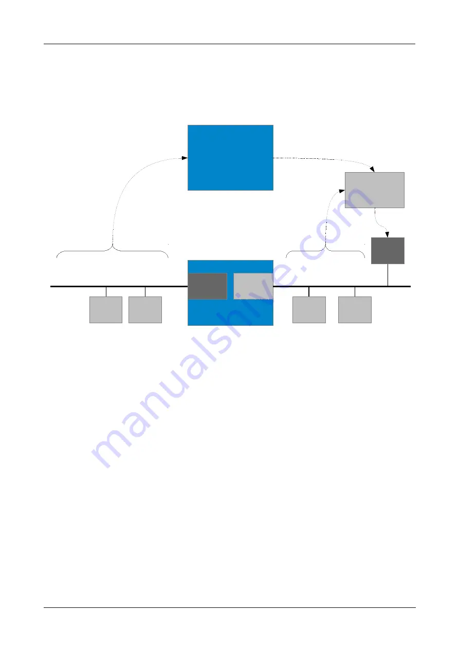
Figure 4:

 Block circuit diagram GSDML Composer

The configuration of the CANopen side of the gateway is performed with the GSDML Composer,
the PROFINET IO side is usually configured via a so called engineering tool (e.g. SIMATIC-S7).

The   CANopen-PN   is   CANopen   master   and   cannot   be   used   as   CANopen   slave.   The   internal
CANopen slave is implicitly used by the PROFINET slave.

The EDS files with information about the CANopen slaves which are required on CANopen side,
must be imported in the GSDML Composer. 

The   GSD   file   for   the   description   of  CANopen-PN  as   PROFINET   IO   slave,   which   is   used   on
PROFINET IO side, is generated with the GSDML Composer.
Thus the GSD file contains all information, the PROFINET IO control needs for the operation of the
Gateway,  and the information, the CANopen Manager integrated in the gateway needs for his
CANopen net.

CANopen-PN

Manual • Doc. No.: C.2921.21 / Rev. 1.6

Page 17 of 105

CANopen-PN

CANopen

Master/Slave

PN

Slave

CAN

Ethernet

GSDML

Composer

...

...

EDS

GSD

GSD

PN

Engineering-

Tool

PN

Slave

PN

Slave

CANopen

Slave

CANopen

Slave

PN

IO-Controller

Summary of Contents for C.2921.02

Page 1: ...teway Manual to Product C 2921 02 CANopen PN Manual Doc No C 2921 21 Rev 1 6 Page 1 of 105 esd electronic system design gmbh Vahrenwalder Str 207 30165 Hannover Germany http www esd eu Phone 49 0 511...

Page 2: ...are subject to esd electronics s written approval 2020 esd electronics gmbh Hannover esd electronics gmbh Vahrenwalder Str 207 30165 Hannover Germany Phone 49 511 372 98 0 Fax 49 511 372 98 68 E Mail...

Page 3: ...of CANopen PN firmware and specific GSDML Composer versions inserted 5 1 3 New chapter Compatibility CANopen PN Firmware and GSDML Composer 5 2 Note to compatibility of CANopen PN firmware and specifi...

Page 4: ...ude a warning relating to property damage DANGER Danger statements indicate a hazardous situation which if not avoided will result in death or serious injury WARNING Warning statements indicate a haza...

Page 5: ...or PELV according to EN 60950 1 complies with this conditions Qualified Personnel This documentation is directed exclusively towards personnel qualified in control and automation engineering The inst...

Page 6: ...ull or stdio h Function names open Programming constants NULL Programming data types uint32_t Variable names Count Number Representation All numbers in this document are base 10 unless designated othe...

Page 7: ...ttings 25 5 4 3 1 Project settings 25 5 4 4 Menu Item Window 25 5 5 Device Library 26 5 5 1 Add CANopen Devices to the current Project 26 5 5 2 Edit Device Library 27 5 6 CANopen Network Editor 28 5 6...

Page 8: ...rface 71 7 5 DIAG Serial Interface via USB Interface 71 7 6 Software Support 72 8 Interfaces and Connector Assignments 73 8 1 CAN 73 8 2 PROFINET IO 74 8 3 24V Power Supply Voltage 75 8 4 24V and CAN...

Page 9: ...pen PN 94 11 7 1 CiA Specification CiA 301 Objects 94 11 7 2 Objects of CiA Specification CiA 302 2 96 12 Appendix InRailBus Option 97 12 1 Connector Assignment 97 12 2 Using InRailBus Option 98 12 3...

Page 10: ...neral data of the module 69 Table 9 Microcontroller units 70 Table 10 Data of the CAN interface 70 Table 11 Data of PROFINET IO interface 71 Table 12 Data of the USB interface 71 Table 13 Conductor co...

Page 11: ...Installation was completely successful 49 Figure 29 Devices and networks 50 Figure 30 Choose the version detail 51 Figure 31 Program window with new CANopen PN in the window Network view 51 Figure 32...

Page 12: ...atible to IEEE802 3 and runs at 100 Mbit s The PROFINET IO and the CANopen interface are electrically isolated against the other components The PROFINET IO interface is equipped with two RJ45 sockets...

Page 13: ...th Connectors Figure 2 Connecting diagram of CANopen PN See also page 73 for signal assignment of the CAN connectors CANopen PN Manual Doc No C 2921 21 Rev 1 6 Page 13 of 105 Musterbild Anschlussplan...

Page 14: ...LED Colour Indicator state Meaning Link green off no Ethernet connection on Ethernet connection is established Activity yellow off no Ethernet connection blinking Ethernet connection is established da...

Page 15: ...flash Error Control Event a Heartbeat or Nodeguard error occurred on the CAN controller is Bus off P green PROFINET IO off no valid PROFINET IO link LED1C on valid PROFINET IO link is established C gr...

Page 16: ...d offers special T connectors and termination connectors Additionally the CAN_GND signal has to be connected to earth at exactly one point in the CAN network A CAN participant with a CAN interface whi...

Page 17: ...n slave is implicitly used by the PROFINET slave The EDS files with information about the CANopen slaves which are required on CANopen side must be imported in the GSDML Composer The GSD file for the...

Page 18: ...for the usage of the esd CANopen PN gateway with the corresponding CANopen net in PROFINET IO 5 1 2 System Requirements Operating system Microsoft Windows XP or newer with Microsoft NET Framework Ver...

Page 19: ...with its tools can be installed to use the CAN interface of the CANopen PN under Windows Therefore select Incl tools for CAN diagnostics in the Select Components window during installation see Figure...

Page 20: ...rol Panel in the start menu Figure 6 CAN Control Panel When the CAN Control Panel window is opened it does already contain the entry of the Net number in the field Virtual CAN port The Net number is 1...

Page 21: ...tton Now all CAN frames received by the CANopen PN are shown depending on the configuration of the ID filter as displayed in the upper left of the CANreal window To transmit frames specify the CAN ID...

Page 22: ...s of the CANopen devices that shall be used into the device library 27 3 Insert the selected devices in the CANopen Network Editor now see chapter 5 6 e g per double click or per Drag n Drop see chapt...

Page 23: ...f the GSDML Composer Legend 1 Menu bar see 5 4 f 2 Toolbar see 5 4 1 3 Device Library see 5 5 4 CANopen Network Editor see 5 6 5 Device Editor in background see 5 9 6 Configuration of the CANopen Net...

Page 24: ...plete project data including the EDS information of the slaves it can thus be opened in the GSDML Composer without importing the EDS files again Save project as As Save Project but file name and path...

Page 25: ...dow Language Changes the language of the GSDML Composer The change will only take effect after an application restart GSDML File name with time Defines whether the name of the GSD file will contain th...

Page 26: ...t as last device 3 Drag n Drop Click with the left mouse button on an entry in the device library hold the button and move the cursor to the CANopen Network Editor Release the mouse button in an empty...

Page 27: ...may therefore not be copied back or used somewhere else Delete from slave library Deletes the selected device from the library Change default image Shows a dialogue for the selection of a new graphic...

Page 28: ...mouse button on a device in the CANopen Network Editor window to open the Device Editor see 5 9 of the respective device A single click opens a small information window which contains e g name and no...

Page 29: ...e the device with the lowest ID becomes the first then the connection line is drawn to the device with the next higher ID etc 5 6 2 Device Context Menu Open device editor Opens the Device Editor see 5...

Page 30: ...g ShutdownAtProfinetFailure ShutdownCommand BootTime BootDelay ConfigureHeartbeat Defines whether the heartbeat objects of the slaves are written For the value False the heartbeat settings defined via...

Page 31: ...cified here the CommunicationCyclePeriod has to be entered in s SynchronousWindowLength Currently not evaluated SyncCounter Currently not evaluated ConfigurePdo Determines whether the PDO objects of t...

Page 32: ...n try to start the modules after the failure is ended In this case the command Reset Controller see 6 1 15 must be called to restart the CANopen boot process after the problem has been resolved BootDe...

Page 33: ...details see Figure 14 With Filter the messages can be filtered by a user defined text Only the messages which contain this text in the Text column are displayed Via the Clear button the filter can be...

Page 34: ...formation Example CAN CBX PT100 INFORMATION For basic information about CANopen refer to chapter CANopen Firmware on page 88 For further information please read the CANopen profile CiA 301 2 5 9 1 Dev...

Page 35: ...arameters top centre and the Communication Parameters Figure 16 PDO Mapping Object selection Figure 6 top left This list shows all objects that can be mapped in a PDO Defined in the EDS file by PDOMap...

Page 36: ...parameters do only apply for TPDOs see chapter 5 9 3 5 9 2 1 Change Mapping Parameter via Buttons Insert an object in a PDO With the button the object selected in the field Object selection is insert...

Page 37: ...0xFF Event based profile specific SYNC Transmission will be triggered at reception of a SYNC message and within the SYNC time window Event based The transmission is independent of the SYNC Inhibit Tim...

Page 38: ...aves SDO Timeout The maximum period in ms the CANopen Manager waits during an SDO request for the answer of the slave Verify Device Type 1000 Defines whether the slave may only be started if the devic...

Page 39: ...s may be transmitted Only applicable for synchronised PDOs i e PDOs with Transmission Type 0xF0 TIME Parameter Node generates TIME messages Defines whether this slave generates the TIME messages of th...

Page 40: ...0 to keep the Node Guarding enabled Heartbeat Heartbeat Producer Heartbeat Time If a value greater than 0 is specified here this slave is Heartbeat Producer and generates Heartbeat messages in the int...

Page 41: ...search function Search Objects of the device manager Figure 15 page 34 bottom left on the page Search results a list with all objects is generated whose name contain the specified text If a four digi...

Page 42: ...value differs from default value Data type Data type of the object DataType in EDS Min Minimum value LowLimit in EDS Max Maximum value HighLimit in EDS Type Type of the object ObjectType in EDS Acces...

Page 43: ...dow Install GSD Files opens Figure 19 Install GSD files Select the GSD file you want to install and confirm the selection with the button Install see Figure 19 The GSD file will be installed now After...

Page 44: ...ft window area In the table bottom left only the CANopen PN and the properties contained in the GSD file are displayed To open the Properties window double click with the left mouse button on a row in...

Page 45: ...etc are displayed For further information about the parameters see chapter 5 7 Figure 21 CANopen Manager properties Example 2 Properties Node Configuration In this example the properties of the first...

Page 46: ...own For further information about the parameters see chapters 5 9 2 or 5 9 3 Figure 23 RPDO TPDO INFORMATION The number of PDO pairs TPDO RPDO T RPDO is limited to 15 per connected CANopen participant...

Page 47: ...Composer that is compatible with the CANopen PN firmware version 1 0 6 before you start with the software configuration 1 Disconnect the online connection in your TIA Portal because the hardware and...

Page 48: ...gure 24 Now the window Manage general station description files opens If the path to the folder is not already entered in the input field Source path correctly click onto the button in the upper right...

Page 49: ...ow now Activate the corresponding check box on the left to select a file see Figure 27 Click onto the button Install to confirm the selection Figure 28 Installation was completely successful If the in...

Page 50: ...dow onto Devices networks as shown in the following figure Figure 29 Devices and networks Choose now your CANopen PN device the in the tree structure of the Hardware Catalogue which is in the right pa...

Page 51: ...ESD CANOPEN PN CONFIG _0150829 20150908 164646 XML The name of the file is composed of the preceding GSDML_V2 3_ ESD CANOPEN PN which is created by the GSDML Composer and following Project name Date T...

Page 52: ...igure 32 To assign the device click onto the button Not assigned Figure 33 Select IO controller The drop down menu Select IO controller is opened In this example the PLC_1 PROFINET Interface_1 can be...
Page 53: ...ftware only Changes You must be still in offline mode for this Figure 34 Compile Hardware and Software detail The configuration is compiled Continue to work offline Now the hardware and software can b...

Page 54: ...ine Figure 36 Toolbar with button Go online The online connection is now established In the program window the components of the decentralised periphery are marked with check marks The I O addresses o...

Page 55: ...put BUSY BOOL Output ERROR BOOL Output STATUS DWORD Output RECORD ANY I O To the function block SFB 53 WRREC a data block DBx here has to be added The data block will be automatically generated when t...

Page 56: ...espective chapters 6 1 1 6 1 17 MLEN minimum length of the bytes to be read e g for Get Version 28 bytes The actually received length of the data is returned in LEN VALID 1 this read operation is comp...

Page 57: ...d for PROFINET IO All other objects are transmitted unchanged The parameter of the following reading Read Service are defined as follows PROFINET IO Read Service Index Parameter Description Value rang...

Page 58: ...does not match length of service parameter too low 11 0 0xB0 0x0609 0011 Sub index does not exist 11 8 0xB8 0x0609 0030 Invalid value for parameter download only 11 3 0xB3 0x0609 0031 Value of paramet...

Page 59: ...re supported and the byte order Endianness is swapped according to the entry in the table 4 Swapping yes or not Swapping no Data Type Value Swapping Boolean 0x01 no Integer8 0x02 no Integer16 0x03 yes...

Page 60: ...s service can start a single CANopen node Node ID node number from 0x01 up to 0x7F i e the node is transferred into CANopen state Operational If Node ID contains the value 0 all CANopen nodes will be...

Page 61: ...resets a single CANopen node Node ID node number Might be necessary if an error occurred during boot up of the slave and the CANopen Manager has terminated the boot up for this reason PROFINET IO Writ...

Page 62: ...lows CAN Bit Timing Bit rate kbit s 0 1000 1 800 2 500 3 250 4 125 5 100 6 50 7 20 8 10 6 1 10 Set Heartbeat Producer 0xB754 By means of this service the Heartbeat Producer time of the CANopen PN can...

Page 63: ...ssages to the PROFINET IO side Per default the forwarding is enabled Therefore this service is only useful if the forwarding has been disabled before see chapter 6 1 13 The parameters are not evaluate...

Page 64: ...t firmware 0xXXXX YYZZ depending on version Version XXXX YY ZZ unsigned 32 4 Serial number 0 0xFFFF FFFF unsigned 32 5 Gateway class 0x0000 0003 unsigned 32 6 Protocol version 0x0001 0100 unsigned 32...

Page 65: ...ta type 0xB772 1 CANopen Node ID 0x01 0x7F unsigned 8 6 1 17 Stop Controller 0xB773 This service stops the CANopen Manager in the CANopen PN The parameter is not evaluated Normally this service should...

Page 66: ...e of this SFB 0 only parameter NEW and LEN are written 1 all output parameters are rewritten 2 all output parameters are rewritten if F_ID has triggered the alarm F_ID logical start address of the sel...

Page 67: ...ister Object 0x1001 see table 7 and 2 31 User Data 3 Manufacturer Specific Emergency Data 5 octets see manual of the CANopen device 36 Length of the data 36 Table 5 Emergency Mapping Alarm specifier s...

Page 68: ...0 recovered from bus off 0x8150 CAN ID collision 0x82xx Protocol error 0x8210 PDO not processed due to length error 0x8220 PDO length exceeded 0x8230 DAM MPDO not processed destination object not avai...

Page 69: ...interface and power supply voltage via InRailBus X5 5 pin ME MAX TBUS connector accessories The following interface is only for test and diagnosis DIAG DIAG interface X3 USB socket type B Temperature...

Page 70: ...11898 1 integrated in SPEAr320S Electrical isolation CAN interface isolated by digital isolators and DC DC converter Physical CAN Layer Physical layer according to ISO 11898 2 transmission rate progr...

Page 71: ...integrated transformer Controller ERTEC400 Connector PORT1 PORT2 X4 2x RJ 45 socket with integrated transformer and LEDs Table 11 Data of PROFINET IO interface 7 5 DIAG Serial Interface via USB Inter...

Page 72: ...tion of the CANopen side of the gateway is done via the GSDML Composer The GSDML Composer is used for generation and parametrization of a GSD file for the CANopen PN The PROFINET IO side of the CANope...

Page 73: ...ctor connection and conductor cross section see page 77 Pin Position Pin Assignment line connector Imprint Signal Pin G CAN_GND 1 L CAN_L 2 Sh Shield 3 H CAN_H 4 5 Signal Description CAN_L CAN_H CAN s...

Page 74: ...The pins 1 to 8 are connected to line terminations Signal Description MDI0 MDI1 PROFINET IO data lines reserved for future applications do not connect Shield case shield connected to earth potential F...

Page 75: ...tor cross section see page 77 Pin Position Pin Assignment Imprint of the housing 24V M P Imprint of the connector none none Pin no 1 2 3 4 Signal Do not connect Do not connect M24 GND P24 24 V Please...

Page 76: ...InRailBus in the appendix 8 5 DIAG The CANopen PN realises a virtual network interface Via this interface firmware can be updated and CAN messages can be recorded and transmitted via the implemented...

Page 77: ...ctor cross section stranded with ferrule with plastic sleeve max 2 5 mm 0 5 mm Conductor cross section AWG kcmil min 24 26 Conductor cross section AWG kcmil max 12 16 2 conductors with same cross sect...

Page 78: ...e the original ISO 11898 They have made system level tradeoffs for data rate cable length and parasitic loading of the bus However for CAN network design margin must be given for signal loss across th...

Page 79: ...al CAN_GND has to be connected to the functional earth FE at exactly one point 4 A CAN net must not branch exception short cable stubs and has to be terminated with the characteristic impedance of the...

Page 80: ...is equipped at the CAN interface at the end of the bus is connected this one has to be used for termination instead of an external CAN termination plug 9 pin DSUB termination connectors with integrate...

Page 81: ...bs and has to be terminated with the characteristic impedance of the line generally 120 10 at both ends between the signals CAN_L and CAN_H and not to CAN_GND 5 Keep cable stubs as short as possible l...

Page 82: ...T connector can be used in which the shield potential is looped through e g the DSUB9 connector from ERNI ERBIC CAN BUS MAX order no 154039 If a mixed application of single twisted and double twisted...

Page 83: ...oss section depending on the cable length are described in the CiA recommendation CiA 303 1 see CiA 303 CANopen Recommendation Part 1 Cabling and connector pin assignment Version 1 8 0 Table 2 Bit Rat...

Page 84: ...Germany www concab de e g BUS PVC C 1x 2x 0 22 mm Order No 93 022 016 UL appr BUS Schleppflex PUR C 1x 2x 0 25 mm Order No 94 025 016 UL appr 9 6 2 Cable for heavy industrial Environment Applications...

Page 85: ...eries resistance of the CAN data pair conductors and the attached terminating resistors To test it please 1 Turn off all power supplies of the attached CAN nodes 2 Measure the DC resistance between CA...

Page 86: ...mit data if there is a short circuit between CAN_GND and CAN_L but generally the error rate will increase strongly Make sure that there is no short circuit between CAN_GND and CAN_L 10 4 CAN_H CAN_L V...

Page 87: ...etwork see figure below 2 Measure the DC resistance between CAN_H and CAN_GND see figure below 3 Measure the DC resistance between CAN_L and CAN_GND see figure below The measured resistance has to be...

Page 88: ...to transmit up to 8 bytes process data In the Receive PDO RPDO the process data are received In the Transmit PDO TPDO the process data are transmitted SDOs Service Data Objects SDOs are used to trans...

Page 89: ...n this directory is addressed with a 16 bit index The index in the object directories is represented in hexadecimal format The index can address parameters defined in CANopen specification or a manufa...

Page 90: ...COB ID 0x047F Description of the SDOs Identifier The parameters are transmitted with ID 0x600 NodeID request The receiver acknowledges the parameters with ID 0x580 NodeID response Command code The com...

Page 91: ...n Download 0x60 Read Request Initiate Domain Upload 0x40 Read Response Initiate Domain Upload 1 2 3 4 0x4F 0x4B 0x47 0x43 Error Response Abort Domain Transfer 0x80 Index Sub Index Index and sub index...

Page 92: ...SDO_VALUE_TOO_LOW transmitted parameter is below the accepted value range 0x08000000 SDO_OTHER_ERROR undefined cause of error 0x08000021 SDO_LOCAL_CONTROL request can not be executed because of the o...

Page 93: ...tart Preoperational Operational 0 NMT 2 0x80 xx Operational Preoperational 0 NMT 2 0x81 xx Reset 0 NMT 2 0x82 xx Reset Communication 0x80 SYNC 0 Sync at all 0x80 Node ID EMCY 0 8 Bytes Error code Emer...

Page 94: ...rw defined via composer 0x1008 Manufacturer Device Name visible string ro CANopen PN 0x1009 Manufacturer Hardware Version visible string ro x yy depending on version 0x100A Manufacturer Software Versi...

Page 95: ...he TPDOs of the slaves connected as defined in the composer 0x1800 0x19FF TPDO Communication Parameter TPDO Communication Parameter of CANopen PN according to the number of PDOs of the RPDOs of the sl...

Page 96: ...2 For a detailed description of the objects refer to CiA 302 2 3 Index Object code Description Data type Access 0x102A VAR NMT inhibit time unsigned16 rw 0x1F80 VAR NMT startup unsigned32 rw 0x1F81 A...

Page 97: ...GY Connector View Pin Assignment Pin Signal 5 M24 GND 4 P24 24 V 3 CAN_GND 2 CAN_L 1 CAN_H S FE PE_GND Signal Description CAN_L CAN_H CAN signals CAN_GND reference potential of the local CAN Physical...

Page 98: ...Bus please proceed as follows Figure 45 Mounting rail with bus connector 1 Position the InRailBus connector on the mounting rail and snap it onto the mounting rail using slight pressure Plug the bus c...

Page 99: ...by the DIN rail bus connector 4 When mounting the CAN CBX module the metal foot catch snaps on the bottom edge of the mounting rail Now the module is mounted on the mounting rail and connected to the...

Page 100: ...socket on the right of the mounting rail bus connector of the InRailBus as described in Figure 48 Then connect the CAN interface and the power supply voltage via the terminal plug 12 3 2 Connection of...

Page 101: ...cause this would cause incorrect branching A bus termination must be connected to the CAN connector of the CAN CBX module at the end of the CBX InRailBus see Fig 50 if the CAN bus ends there 12 4 Remo...

Page 102: ...Proposal CANopen additional application layer Part 2 Network management CAN in Automation e V N rnberg Germany V 4 1 02 2009 4 CiA 306 WD Electronic device description Part 1 Electronic Data Sheet and...

Page 103: ...Declaration of Conformity 14 Declaration of Conformity CANopen PN Manual Doc No C 2921 21 Rev 1 6 Page 103 of 105...

Page 104: ...PROFINET IO Certificate 15 PROFINET IO Certificate Page 104 of 105 Manual Doc No C 2921 21 Rev 1 6 CANopen PN...

Page 105: ...er supply voltage and the CAN interface Male type C 3000 03 Table 16 Order information PDF Manuals Manuals are available in English and usually in German as well For availability of English manuals se...

Reviews: