T3-B T6-B Manipulator 5. Motion Range
84
T-B series Rev.1
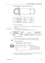
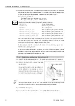
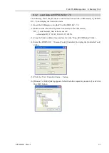
Execute the following commands from the [Command Window]. Enter the value
calculated in Step (9) in X.
>MOTOR ON
' Turns ON the motor
>SPEED 5
' Sets low speed
>PULSE 0,0,X,0
' Moves to the lower limit-pulse position of Joint #3.
(In this example, all pulses except those for Joint #3 are “0”.
Substitute these “0s” with the other pulse values specifying
a position where there is no interference even when lowering
Joint #3.)
5.3 Setting the Cartesian (Rectangular) Range in the XY
Coordinate System of the Manipulator (for Joints #1 and #2)
Use this method to set the upper and lower limits of the X and Y coordinates.
This setting is only enforced by software. Therefore, it does not change the physical range.
The maximum physical range is based on the position of the mechanical stops.
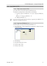
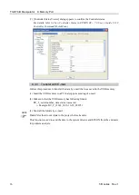
Set the XYLim setting on the [XYZ Limits] panel shown by selecting [Tools]-[Robot
Manager].
(You may also execute the XYLim command from the [Command Window].)
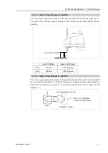
5.4 Standard Motion Range
The following “motion range” diagrams show the standard (maximum) specification. When
each Joint motor is under servo control, the center of Joint #3’s (shaft’s) lowest point moves
in the areas shown in the figure.
“Area limited by mechanical stop” is the area where the center of Joint #3’s lowest point
can be moved when each joint motor is not under servo control.
“Mechanical stop” sets the limited motion range so that the center of Joint #3 cannot move
beyond the area mechanically.
“Maximum space” is the area that contains the farthest reach of the arms. If the maximum
radius of the end effector is over 60 mm, add the “Area limited by mechanical stop” and
“radius of the end effector”. The total value is specified as the maximum area.
For the motion area figures, refer to “
3.3 Mounting Dimensions
”.
EPSON
RC+
EPSON
RC+
Summary of Contents for T-B Series
Page 1: ...SCARA ROBOT T B series MANUAL Rev 1 EM217R4788F ...
Page 2: ...SCARA Robots T B series Manual Rev 1 ...
Page 16: ...TABLE OF CONTENTS xiv T B series Rev 1 ...
Page 18: ......
Page 40: ...Installation 5 Second Step 24 T B series Rev 1 ...
Page 42: ......
Page 58: ...T3 B T6 B Manipulator 2 Specifications 42 T B series Rev 1 2 3 Outer Dimensions 2 3 1 T3 B ...
Page 59: ...T3 B T6 B Manipulator 2 Specifications T B series Rev 1 43 2 3 2 T6 B ...
Page 77: ...T3 B T6 B Manipulator 3 Environments and Installation T B series Rev 1 61 T6 B A B ...
Page 158: ...T3 B T6 B Manipulator 18 Error Code List 142 T B series Rev 1 ...
Page 160: ......
Page 168: ......
Page 178: ...Appendix B Time and Distance of Free Running in Emergency 162 T B series Rev 1 ...
Page 182: ...Appendix C Time and Distance of Free Running When Safeguard Is Opened 166 T B series Rev 1 ...


