T3-B T6-B Manipulator 11. EMERGENCY
T-B series Rev.1
107
11.3 Pin Assignments
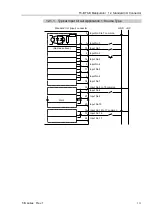
The EMERGENCY connector pin assignments are as follows: (D-Sub 25 pin male)
Pin No.
Signal
Function
Pin No.
Signal
Function
1
ESW11
Emergency Stop switch contact (1)
*3
14 ESW21
Emergency Stop switch contact (2)
*3
2
ESW12
Emergency Stop switch contact (1)
*3
15 ESW22
Emergency Stop switch contact (2)
*3
3
Emergency Stop circuit 1 (+)
*4
16
Emergency Stop circuit 2 (+)
*4
4
ESTOP1-
Emergency Stop circuit 1 (
-
)
*4
17 ESTOP2-
Emergency Stop circuit 2 (
-
)
*4
5
Not Used
*1
18 SDLATCH1
Safeguard Latch Release
6
Not Used
*1
19 SDLATCH2
Safeguard Latch Release
7
SD11
Safeguard input (1)
*2
20 SD21
Safeguard input (2)
*2
8
SD12
Safeguard input (1)
*2
21 SD22
Safeguard input (2)
*2
9
24V
+24V output
22 24V
+24V output
10 24V
+24V output
23 24V
+24V output
11 24VGND
+24V GND output
24 24VGND
+24V GND output
12 24VGND
+24V GND output
25 24VGND
+24V GND output
13
Not Used
*1
*1 Do not connect anything to these pins.
*2 A critical error occurs if the input values from the Safeguard 1 and Safeguard 2 are
different for two or more seconds. They must be connected to the same switch with
two sets of contacts.
*3 A critical error occurs if the input values from the Emergency Stop switch contact 1
and Emergency Stop switch contact 2 are different for two or more seconds. They must
be connected the same switch with two sets of contacts.
*4 Do not apply reverse voltage to the Emergency Stop circuit.
Emergency Stop switch output rated load
+30 V 0.3 A or under
1-2, 14-15 pin
Emergency Stop rated input voltage range
Emergency Stop rated input current
+24 V
±
10%
37.5 mA
±
10% /+24 V input
3-4, 16-17 pin
Safeguard rated input voltage range
Safeguard rated input current
+24 V
±
10%
10 mA/+24 V input
7-8, 20-21 pin
Latch Release rated input voltage range
Latch Release rated input current
+24 V
±
10%
10 mA/+24 V input
18-19 pin
The total electrical resistance of the Emergency Stop switches and their circuit should be 1
Ω
or less.
CAUTION
■
The 24 V output is for emergency stop. Do not use it for other purposes. Doing so
may result in system malfunction.
■
Do not apply reverse voltage to the Emergency Stop circuit. Doing so may result
in system malfunction.
NOTE
Summary of Contents for T-B Series
Page 1: ...SCARA ROBOT T B series MANUAL Rev 1 EM217R4788F ...
Page 2: ...SCARA Robots T B series Manual Rev 1 ...
Page 16: ...TABLE OF CONTENTS xiv T B series Rev 1 ...
Page 18: ......
Page 40: ...Installation 5 Second Step 24 T B series Rev 1 ...
Page 42: ......
Page 58: ...T3 B T6 B Manipulator 2 Specifications 42 T B series Rev 1 2 3 Outer Dimensions 2 3 1 T3 B ...
Page 59: ...T3 B T6 B Manipulator 2 Specifications T B series Rev 1 43 2 3 2 T6 B ...
Page 77: ...T3 B T6 B Manipulator 3 Environments and Installation T B series Rev 1 61 T6 B A B ...
Page 158: ...T3 B T6 B Manipulator 18 Error Code List 142 T B series Rev 1 ...
Page 160: ......
Page 168: ......
Page 178: ...Appendix B Time and Distance of Free Running in Emergency 162 T B series Rev 1 ...
Page 182: ...Appendix C Time and Distance of Free Running When Safeguard Is Opened 166 T B series Rev 1 ...


