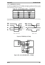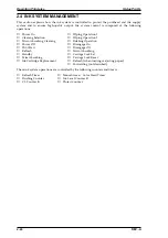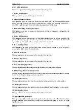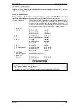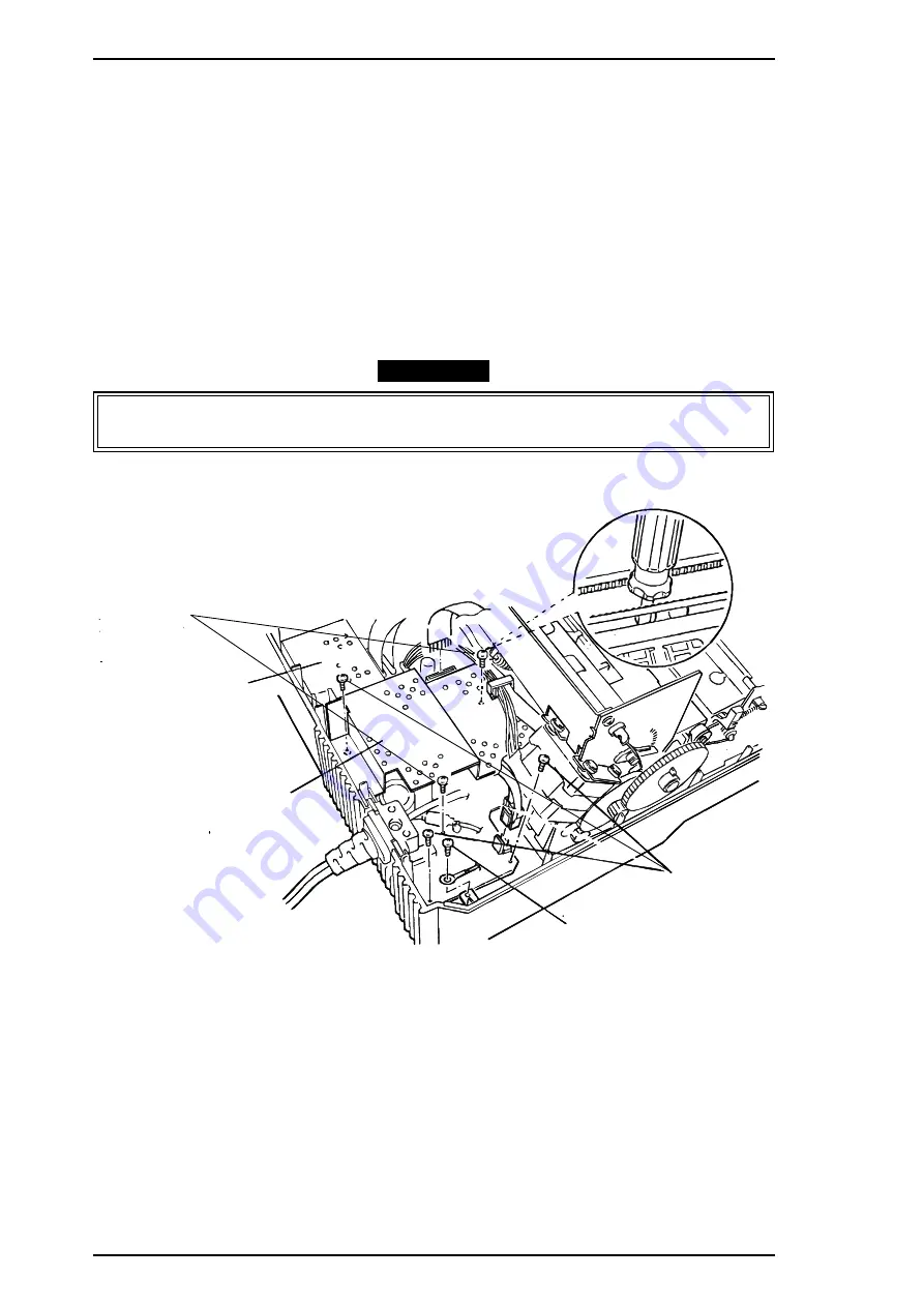
3.2.2 Power Supply Unit (C137 PSB/PSE Board) Removal
1.
Remove the upper case (see Section 3.2.1).
2.
Disconnect the cables from connectors CN1 on the C137 PSB /PSE Board and CN5 on the C162
MAIN Board.
3.
Remove the 2 screws, 1 CBN (M3
×
8) and 1 CBB (M3
×12)
, securing the shield plate to the lower
case via the C137 PSB/PSE Board.
4.
Remove the 3 screws, 2 CBB (M3
×
12) and 1 CBN (M3
×
8), securing the C137 PSB/PSE Board to
the lower case, and remove a CBN (O) (M3
×
6) screw fixing the earth line from the AC cable to
the earth plate.
5.
Remove the wire harness for the motors in the locking tab on the shield plate, and take the
shield plate out by pulling upward toward the back of the printer.
6.
Remove the power supply unit by pulling it upward toward the back of the printer.
CAUTION
The shield plates of C137 PSB/PSE and C162 MAIN boards have sharp edges, so take care
in handling them.
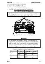
CBS (M3x8)
C162 MAIN Board
C137 PSB Board
CBS(O) (M3x6)
CBB (M3x12)
Figure 3-4. Power Supply Unit Removal
Disassembly and Assembly
Stylus Pro XL
3-4
REV.-A
Summary of Contents for Stylus Pro XL
Page 1: ...EPSON COLOR INKJET PRINTER Stylus Pro XL SERVICE MANUAL EPSON 4004677 ...
Page 93: ...Rev A 5 i ...
Page 127: ...EPSON ...

