EPSON Stylus Pro 7500
Revision A
Adjustment
Adjustment Steps
191
5.2.3.4 Adjustment Menu
The Adjust menu allows you to make certain adjustments to the printer mechanism and
controls, for example head angle adjustment, print position adjustment, paper feeding
correction, and firmware-control setting.
*1 These should definitely be executed after the new C299MAIN board has
been installed.
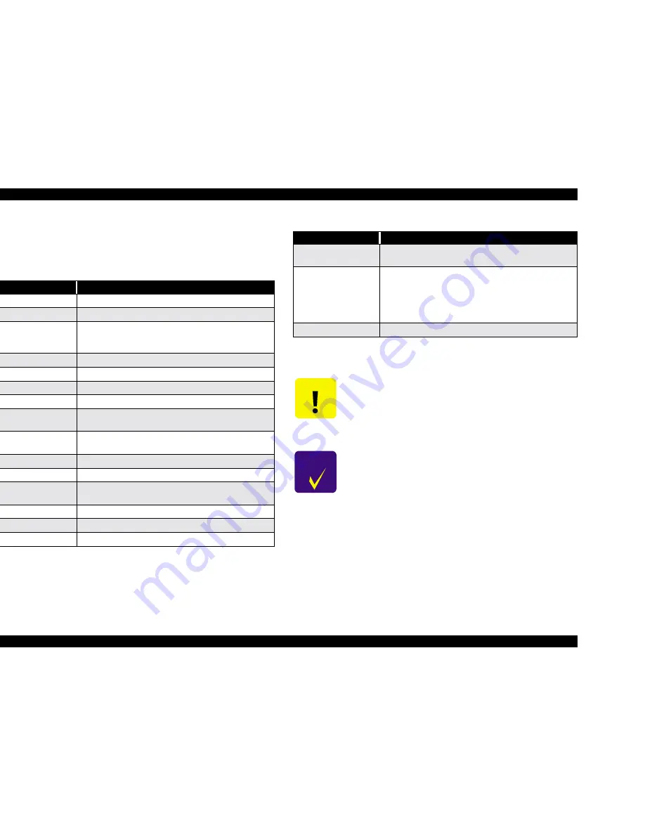
Table 5-9. Adjustment Menu Items
Adjustment Item
Description
Capping Position
Sets the Capping position (automatic Adjustment)
Paper Skew Check
Verifies the degree of skew (slant) allowed during printing
Write D/A Value
Writes the direct/alternate data to the Flash ROM; *1 compensates
for differences in individual Main Boards - like head ID for the
Main Board
Head Rank Input
Sets the printhead ID
Head Nozzle Check
Prints the check pattern to make sure the nozzles are not clogged
B Head Angle
Adjusts the angle of the B Head (mechanism adj.)
C Head Angle
Adjusts the angle of the C Head (mechanism adj.)
BC Head Height
Verifies the B/C Head nozzles are at the same height (mechanism
adj.)
Bi-D Print Position
Verifies the printed lines match up when performing bi-directional
printing.
Head Gap
Adjusts the B/C Head Gap as well as sets the left margin
R Flush Point
Adjusts the flush position on the HP side
L Flush Point
Do not use, there is no left flush point and this function will
generate a fatal error
Feed Correction
Checks paper feeding (w/ruler)
Top & Bottom
Checks the top and bottom margins (w/ruler)
Rear Paper Sensor Position Sets the detection position of the rear paper-edge sensor
Test Pattern Print
Checks print quality (prints setting information, check pattern and
so on)
Clean Head
Initiates cleaning/flushing of the heads and ink path
1) Ink drain
2) Fill with transportation fluid (1 time = 15ml)
3) Drain transportation fluid
4) Reset the ink charge flag
Counter Clear
Resets all counters in Table 5-13 on page 210
C A U T I O N
n
Use the transport liquid cartridges (x 6) for “Head Cleaning.” It
is also possible to substitute “Transport Liquid Initial Filling -
Transport Mode.”
n
“Counter Clear” should only be carried out during replacement
of periodic replacement parts produced in the “Maintenance Kit,
Stylus Pro 7500,” which includes the waste ink pads.
C H E C K
P O I N T
n
When replacing the C299MAIN board, be sure to carry out
writing of the D/A correction values. This parameter is measured
during manufacturing of the circuit board, and is written to the
USB EEPROM on the board. This parameter exists in a Flash
ROM area that cannot be copied during parameter backup with
a PC card, so it should be carried out from the USB EEPROM on
the new board.
Table 5-9. Adjustment Menu Items (continued)
Adjustment Item
Description
Summary of Contents for Stylus Pro 7500
Page 1: ...EPSONStylusPRO7500 Color Large Format Inkjet Printer SEIJ00005 SERVICE MANUAL ...
Page 6: ...Revision Status Revision Issued Date Description Rev A August 31 2000 First Release ...
Page 10: ...C H A P T E R PRODUCTDESCRIPTION ...
Page 57: ...C H A P T E R OPERATINGPRINCIPLES ...
Page 75: ...C H A P T E R TROUBLESHOOTING ...
Page 95: ...C H A P T E R DISASSEMBLY ASSEMBLY ...
Page 169: ...C H A P T E R 0 ADJUSTMENT ...
Page 192: ...PSON Stylus Pro 7500 Revision A djustment Adjustment Steps 192 Figure 5 13 Adjustment Menu ...
Page 235: ...C H A P T E R MAINTENANCE ...
Page 241: ...C H A P T E R APPENDIX ...
Page 258: ...PSON Stylus Pro 7500 Revision A ppendix Exploded View Diagram 258 Figure 7 2 Frame Assembly ...
Page 260: ...PSON Stylus Pro 7500 Revision A ppendix Exploded View Diagram 260 Figure 7 4 Head Assembly ...
Page 262: ...PSON Stylus Pro 7500 Revision A ppendix Exploded View Diagram 262 Figure 7 6 Frame Accessory ...
Page 265: ...PSON Stylus Pro 7500 Revision A ppendix Exploded View Diagram 265 Figure 7 9 Cable Guide ...
Page 267: ...PSON Stylus Pro 7500 Revision A ppendix Exploded View Diagram 267 Figure 7 11 Cover Assembly ...
Page 272: ......
Page 273: ......
Page 274: ......


