EPSON Stylus Pro 7500
Revision A
Disassembly & Assembly
Disassembly Flow
167
3.
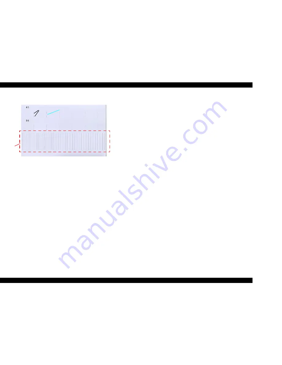
After all the adjustment patterns (#5, #6) are printed, “Gap, 200 , M: XXX” will be
displayed in the LCD.
Figure 4-138. Head Gap Adjustment Pattern
4.
Check printing patterns No. 5 and No. 6, and check for alignment of the black vertical
lines in the 1st and 3rd pass and in the light cyan vertical lines in the 2nd pass.
o
If black vertical lines ans the light cyan vertical line are lined up correctly, in the
patterns in printing patterns No. 5 and No. 6, press the Paper Source button 2
times, then check if the message “GAP END.” is displayed in the LCD. Proceed to
Step 6.
o
If black vertical lines and the light cyan vertical line are not lined up correctly in
the patterns in printing patterns No. 5 or No. 6, press the Paper Source button to
move to the corresponding pattern adjustment menu, then input the appropriate
numerical values using the Paper Feed + / – keys. After inputting the correction
value, press the Enter button to print the results of the input correction values. The
relationship between the inputs using the Paper Feed + / – buttons and the printing
results is as shown below.
n
Adjustment value minimum resolution:1/2880 Inch
n
Correction Direction:
Paper Feed – Button = Moves the black lines in the
1st and 3rd passes toward the HP side.
Paper Feed + Button = Moves the light cyan lines in
the 2nd pass away from the HP side.
n
Adjustment Target:
There should be no deviation in the black lines and
the light cyan lines.
5.
Repeat the above steps 3 and 4 until the adjustment of patterns No. 5 and No. 6 is
completed.
6.
After confirming that “GAP END.” is displayed in the LCD, execute the final check
items.
Black Vertical
Lines
Light Cyan Vertical Lines
This pattern
has no relation
to the Gap
adjustment.
Summary of Contents for Stylus Pro 7500
Page 1: ...EPSONStylusPRO7500 Color Large Format Inkjet Printer SEIJ00005 SERVICE MANUAL ...
Page 6: ...Revision Status Revision Issued Date Description Rev A August 31 2000 First Release ...
Page 10: ...C H A P T E R PRODUCTDESCRIPTION ...
Page 57: ...C H A P T E R OPERATINGPRINCIPLES ...
Page 75: ...C H A P T E R TROUBLESHOOTING ...
Page 95: ...C H A P T E R DISASSEMBLY ASSEMBLY ...
Page 169: ...C H A P T E R 0 ADJUSTMENT ...
Page 192: ...PSON Stylus Pro 7500 Revision A djustment Adjustment Steps 192 Figure 5 13 Adjustment Menu ...
Page 235: ...C H A P T E R MAINTENANCE ...
Page 241: ...C H A P T E R APPENDIX ...
Page 258: ...PSON Stylus Pro 7500 Revision A ppendix Exploded View Diagram 258 Figure 7 2 Frame Assembly ...
Page 260: ...PSON Stylus Pro 7500 Revision A ppendix Exploded View Diagram 260 Figure 7 4 Head Assembly ...
Page 262: ...PSON Stylus Pro 7500 Revision A ppendix Exploded View Diagram 262 Figure 7 6 Frame Accessory ...
Page 265: ...PSON Stylus Pro 7500 Revision A ppendix Exploded View Diagram 265 Figure 7 9 Cable Guide ...
Page 267: ...PSON Stylus Pro 7500 Revision A ppendix Exploded View Diagram 267 Figure 7 11 Cover Assembly ...
Page 272: ......
Page 273: ......
Page 274: ......


