


SC-F2000
Revision C
ADJUSTMENT
TF Adjustments
258
Confidential
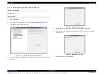
[Blue]:
Button or menu name on the program screen /
[Black]:
Button or menu name on the operation panel of the printer
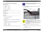
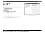
5.
Set the height of the PLATEN to “P”, and secure it with the Fixing Lever.
6.
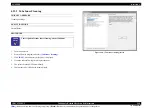
Click
[RUN]
. The TABLE ASSY is moved inside the printer.
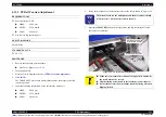
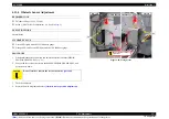
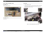
7.
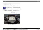
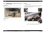
Place the 1.55 thickness gauge in the middle of the home side of the PLATEN.
Figure 4-59. Set position of the thickness gauge on the home side
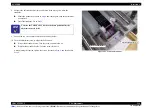
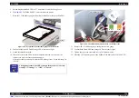
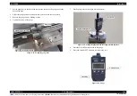
8.
Confirm both Green LED and Orange LED of the sensor light.
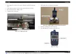
9.
Attach the adjustment screw.
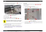
10. Check the color of the LEDs, rotate the adjustment screw on the home side
clockwise to move the sensor position upward.
Adjust the sensor position up to when the LEDs change from “Green & Orange” to
“Green”.
Figure 4-60. The LEDs and adjustment screw on the home side
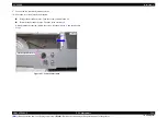
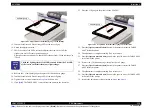
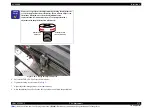
11. Remove the 1.55 thickness gauge, then place the 1.88 gauge.
12. Confirm both Green LED and Orange LED of the sensor light.
13. Tighten the two screws loosened in
14. Place the 1.55 thickness gauge in the middle of the home side of the PLATEN.
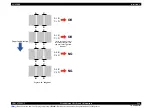
C H E C K
P O I N T
The lighting status of the LEDs changes in the order of “Green &
Orange” => “Orange” => “OFF” => “Green”.
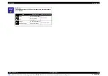
Thickness gauge
LED
Green
Orange
Adjustment screw
Summary of Contents for SC-F2000 Series
Page 1: ...SC F2000 Direct To Garment Printer SERVICE MANUAL SECP13002 Confidential ...
Page 10: ...Confidential C H A P T E R 1 PRODUCTDESCRIPTION ...
Page 29: ...Confidential C H A P T E R 2 TROUBLESHOOTING ...
Page 52: ...Confidential C H A P T E R 3 DISASSEMBLY ASSEMBLY ...
Page 192: ...Confidential C H A P T E R 4 ADJUSTMENT ...
Page 285: ...Confidential C H A P T E R 5 MAINTENANCE ...


