68
EPSON
S1C63656 TECHNICAL MANUAL
CHAPTER 4: PERIPHERAL CIRCUITS AND OPERATION (Stopwatch Timer)
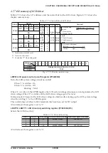
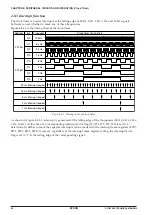
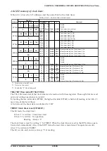
4.9.7 I/O memory of stopwatch timer
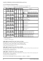
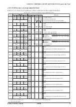
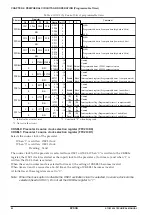
Table 4.9.7.1 shows the I/O addresses and the control bits for the stopwatch timer.
Table 4.9.7.1 Control bits of stopwatch timer
Address
Comment
D3
D2
Register
D1
D0
Name
Init
∗
1
1
0
FF06H
FOUTE SWDIR FOFQ1 FOFQ0
R/W
FOUTE
SWDIR
FOFQ1
FOFQ0
0
0
0
0
Enable
Disable
FOUT output enable
Stopwatch direct input switch
0: K00=Run/Stop, K01=Lap 1: K00=Lap, K01=Run/Stop
FOUT
frequency
selection
0
f
OSC1
/64
1
f
OSC1
/8
2
f
OSC1
3
f
OSC3
[FOFQ1, 0]
Frequency
SWD7
SWD6
SWD5
SWD4
0
0
0
0
Stopwatch timer data
BCD (1/100 sec)
R
FF7BH
SWD7
SWD6
SWD5
SWD4
SWD11
SWD10
SWD9
SWD8
0
0
0
0
Stopwatch timer data
BCD (1/10 sec)
R
FF7CH
SWD11 SWD10
SWD9
SWD8
R
FF7AH
SWD3
SWD2
SWD1
SWD0
SWD3
SWD2
SWD1
SWD0
0
0
0
0
Stopwatch timer data
BCD (1/1000 sec)
0
None
1
K02
2
K02–03
3
K02–03,10
[DKM2, 1, 0]
Key mask
4
K10
5
K10–11
6
K10–12
7
K10–13
[DKM2, 1, 0]
Key mask
R/W
FF78H
EDIR
DKM2
DKM1
DKM0
EDIR
DKM2
DKM1
DKM0
0
0
0
0
Enable
Disable
Direct input enable
Key mask
selection
R/W
W
R
FF79H
LCURF CRNWF SWRUN SWRST
LCURF
CRNWF
SWRUN
SWRST
∗
3
0
0
0
Reset
Request
Renewal
Run
Reset
No
No
Stop
Invalid
Lap data carry-up request flag
Capture renewal flag
Stopwatch timer Run/Stop
Stopwatch timer reset (writing)
FFE6H
EIRUN
EILAP
EISW1 EISW10
R/W
EIRUN
EILAP
EISW1
EISW10
0
0
0
0
Enable
Enable
Enable
Enable
Mask
Mask
Mask
Mask
Interrupt mask register (Stopwatch direct RUN)
Interrupt mask register (Stopwatch direct LAP)
Interrupt mask register (Stopwatch timer 1 Hz)
Interrupt mask register (Stopwatch timer 10 Hz)
FFF6H
IRUN
ILAP
ISW1
ISW10
R/W
IRUN
ILAP
ISW1
ISW10
0
0
0
0
(R)
Yes
(W)
Reset
(R)
No
(W)
Invalid
Interrupt factor flag (Stopwatch direct RUN)
Interrupt factor flag (Stopwatch direct LAP)
Interrupt factor flag (Stopwatch timer 1 Hz)
Interrupt factor flag (Stopwatch timer 10 Hz)
*1 Initial value at initial reset
*2 Not set in the circuit
*3 Constantly "0" when being read
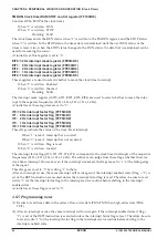
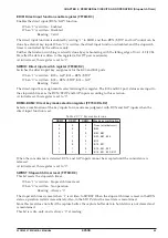
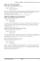
SWD0–SWD3: Stopwatch timer data 1/1,000 sec (FF7AH)
Data (BCD) of the 1/1,000 sec column of the capture buffer can be read out.
The hold function of the capture buffer works by reading this data.
These 4 bits are read-only, and cannot be used for writing operations.
At initial reset, the timer data is set to "0".
SWD4–SWD7: Stopwatch timer data 1/100 sec (FF7BH)
Data (BCD) of the 1/100 sec column of the capture buffer can be read out. These 4 bits are read-only, and
cannot be used for writing operations.
At initial reset, the timer data is set to "0".
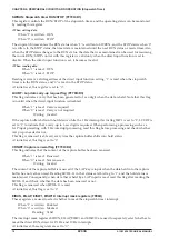
SWD8–SWD11: Stopwatch timer data 1/10 sec (FF7CH)
Data (BCD) of the 1/10 sec column of the capture buffer can be read out. These 4 bits are read-only, and
cannot be used for writing operations.
At initial reset, the timer data is set to "0".
Note: Be sure to data reading in the order of SWD0–3
→
SWD4–7
→
SWD8–11.


