126
EPSON
S1C63656 TECHNICAL MANUAL
CHAPTER 4: PERIPHERAL CIRCUITS AND OPERATION (Stepping Motor Driver)
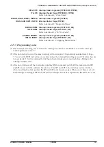
PFTYP: Pulse width base clock register (FF15H•D0)
Selects the source clock to generate motor-drive pulses according to clocks or watches.
When "1" is written: Short pulse (4 kHz)
When "0" is written: Long pulse (512 Hz)
Reading: Valid
When "1" is written to PFTYP, a 4-kHz clock used to generate the short pulse for watch stepping motors is
selected. When "0" is written, a 512-Hz clock used to generate the long pulse for clock stepping motors is
selected. See Table 4.15.5.2 for the pulse widths generated.
At initial reset, this register is set to "0".
EISMD1: Motor driver Ch. 1 interrupt mask register (FFE8H•D0)
EISMD2: Motor driver Ch. 2 interrupt mask register (FFE8H•D1)
Masking the interrupt of the motor driver can be selected with this register.
When "1" is written: Enabled
When "0" is written: Masked
Reading: Valid
EISMD1 and EISMD2 are the interrupt mask registers that respectively correspond to the motor driver
Ch. 1 and Ch. 2 interrupt factors. Interrupts set to "1" are enabled and interrupts set to "0" are disabled.
At initial reset, these registers are set to "0".
ISMD1: Motor driver Ch. 1 interrupt factor flag (FFF8H•D0)
ISMD2: Motor driver Ch. 2 interrupt factor flag (FFF8H•D1)
These flags indicate the status of the motor driver interrupt.
When "1" is read: Interrupt has occurred
When "0" is read: Interrupt has not occurred
When "1" is written: Flag is reset
When "0" is written: Invalid
ISMD1 and ISMD2 are the interrupt factor flags that respectively correspond to the motor driver Ch. 1
and Ch. 2 interrupts, and are set to "1" upon completion of a motor-drive pulse output.
The software can judge from these flags whether there is a motor driver interrupt. However, even
if the interrupt is masked, the flags are set to "1" upon completion of a motor-drive pulse output from the
corresponding channel.
These flags are reset to "0" by writing "1" to them.
After an interrupt occurs, the same interrupt will occur again if the interrupt enabled state (I flag = "1") is
set or the RETI instruction is executed unless the interrupt factor flag is reset. Therefore, be sure to reset
(write "1" to) the interrupt factor flag in the interrupt service routine before shifting to the interrupt
enabled state.
At initial reset, these flags are set to "0".


